Hello Frode,
Yes, 500 V is too high for that circuit. In theory, DC voltage of a choke input filter PS is 0.9 times the AC voltage. So, the 415 V that you get from the raw PS is within normal limits. But, that's too much to feed the SReg in order to get a regulated voltage of 300 V. If my memory serves me well, the total current draw of RTP3C is circa 80 mA per channel. With a drop-out voltage of 120 V, the SReg must stand a power dissipation of 20 Watts - that's way too much.
For a start, I would seriously consider getting a new power transformer with more appropriate ratings.
Regards,
Evangelos
Thank you for your kind reply Evangelos !
You probably right, but as you can see it is limited space inside the chassi, and also this is the transformer delivered by Vacuum State to power this unit. It should be unnesesary for me to buy a new one as I belive they must have thought about this problem ! ?
I wil use the day to think about it.
Sincerely
Frode
Hello,
Allen Wright usually let the shunt circuit take as much current as the circuit itself. So there will be a considerable voltage drop across the input choke. I have been using his circuit in my pwwer amp for decades now. Greetings, Eduard
P.s Take care with the power resistors the resistor inside the alumium houasing can only go outside on the left or the right side and it will one day
Hello Eduard !
If I understand you correctly, do you mean if each channel draw 80 mA, then the shunt circuit also draw 80 mA ? A total of 160 mA for each channel ?
How do you sugest I wil find the corect voltagedrop in the power supply ? What should I fysikly do?
Sincerely
Frode
As Evangelos has said, a choke regulated power supply will only supply the intended voltage if the current draw is what it was designed for. And as he said, there is a theoretical optimum combination of current, voltage and inductance for such a circuit, but you can't guarantee that yours was designed that way. Allen was never one for following accepted wisdom!Hello Eduard !
If I understand you correctly, do you mean if each channel draw 80 mA, then the shunt circuit also draw 80 mA ? A total of 160 mA for each channel ?
How do you sugest I wil find the corect voltagedrop in the power supply ? What should I fysikly do?
Sincerely
Frode
As far as your load resistor goes, I would only use it for testing the output of the shunt regs, since the unregulated voltage is far too high for the rated dissipation.
It would be helpful if you measured the unloaded AC output from the HT secondary - then someone with the Duncan PSUD simulator might be able to confirm whether this is indeed too high for the regulator. I am still surprised that the voltage at the input to the SuperReg is so high, given that yours is a proper VSE kit.
My own RTP3 PSU uses a 300V secondary for the HT, which in retrospect is too low: to get 350VDC after the choke I had to use add about half a microfarad between the rectifiers and the choke, which downgrades the performance of the choke a little. My chokes are also under-specified for current, which means they buzz a little.
Alex
I just had a thought. What is the shunt current set to in your SuperReg? Allen recommended using the same again as the draw from the preamp, although I feel this is excessive, and I set mine to shunt 20mA. Looking at the schematics again, I reckon the RTP3 draws 60-65mA, so ideally you should be testing your PSU with an 80-100mA draw. If your regulator is taking less than this, the HT on the input will higher than intended.
So, given my comments in the last post, we could assume the voltage on the HT transformer is correct without too much risk. What I would suggest is to set up the SuperRegs as per the instruction manual to give 300V onto the dummy load, with about 20mA of shunt current, so you are confident they are functioning properly. Then turn the shunt current down to zero before testing the individual preamp modules, raising it in each case to what is needed of a stable regulated current once the valve heaters have warmed up.
Once you have everything working, re-check the unregulated HT and report back!
Alex
Last edited:
Hello Alex M !
I apriciate you helpfulnes !
The Sreg innstaled in my preamp is new build and never tested before. ( the old ones shorted )
Are you sugesting that I conect the Sreg to 415 vdc and start to adjusting them acording to the description following the Sreg kit ?
Sincerely
Frode
I apriciate you helpfulnes !
The Sreg innstaled in my preamp is new build and never tested before. ( the old ones shorted )
Are you sugesting that I conect the Sreg to 415 vdc and start to adjusting them acording to the description following the Sreg kit ?
Sincerely
Frode
Hello,
The advice of Alex is perfect.
Allen always suggested a minimum current of 20 mA AND depending on the circuit connected you could raise that current ( he said it gave better sonics) But you need to take care about the dissipation of the mosfets.
If you have an high input voltage and a big current draw things might get to hot. So it depends upon how the superreg circuit has been installed. In my situation ( el84 single ended amp) i took both fets from the print and mounted them on a bigger heatsink. They have been in use for twenty years now.
greetings, Eduard
"But you need to take care about the dissipation of the mosfets."
Hello Eduard !
The instruction following the Sreg kit, as I remember are not ment to handle voltage drop this high. If I follow the the manual I am afraid the dissipation of the mosfets wil be to high.
The heat sink on these Sreg are larger than the old ones, but still...
Sincerely
Frode
Hello Eduard !
The instruction following the Sreg kit, as I remember are not ment to handle voltage drop this high. If I follow the the manual I am afraid the dissipation of the mosfets wil be to high.
The heat sink on these Sreg are larger than the old ones, but still...
Sincerely
Frode
The regulators should be able to handle 425V on the input, since the MOSFETS are rated to 500V. As long as the current through either the series or shunt MOSFETs isn't excessive you should be OK. That's why I suggest testing each circuit module independently, gradually winding the shunt current up from zero to whatever is needed to stabilise the regulator.
By the way, I didn't install SuperRegs proper into my VSE preamps until three or four years ago. To start with I built a couple of pairs of Emile Sprenger's HPHV regulator from PCBs I etched in the workshop at work: these have a similar topology to Allen's Sregs, but each part of the circuit is individually regulated. I suspect that my PCBs weren't up to the sophistication of the circuit, as I found them to be unreliable, with the voltage dropping after a few months, along with a hint of RF instability. I replaced these with Nikolaos Salas' SSHV2 regulator, a much simpler design, but found these slightly poorer in their line regulation and slightly noisy. Eventually I succumbed and paid VSE for four SuperReg kits and installed these in my SVP and RTP3 preamps, and found them to be easy to build, extremely reliable and very stable. Surprisingly, given the evolution of the preamp circuits themselves over the years, the regulator is basically the same circuit as in the TPCB from nearly twenty years ago!
Alex
Last edited:
Well, I digged my archives and found a conversation I had way-way back with Allen. I quote part of it regarding the issue here:
>>>From a message you have sent me, I see that each channel of the RTP3C draws about 80mA before any shunt current in the Super Reg. Does this mean that I have to calculate for an outboard larger heatsink?<<<
>No. Not if your input V to the SRegs is what I use: 340VDC.<
And later:
>Now, another question regarding the HT transformer: You use a Tx with a secondary of 500V and drop voltage using the two 120R resistors in front of the bridge and a 180R resistor after the bridge. Is this done intentionally or because you had this Tx?<
>This is a stock transformer available off the shelf - specials are a serious hassle and generally much more expensive. But the filtering provided by the 'extra' resistors interacting with the relevant caps does no harm!<
So, Frode, that brings out the following question: Does you raw power supply have the aforementioned resistors installed?
Regards,
Evangelos
>>>From a message you have sent me, I see that each channel of the RTP3C draws about 80mA before any shunt current in the Super Reg. <<<
I've seen this 80mA figure before, and it doesn't make sense to me. The phono stage draws 19mA; the voltage amplifier stage 2 x 6mA and the output stage 2 x 12mA, totalling 55mA. The filament bias networks only take a milliamp between them, and the voltage divider for the bootstrap valves in the SLCF less than that. Can anyone explain where the other ~25mA goes?
Alex
Dear Alex,
Although I have build the most part of RTP3C, for years now I never managed to sit down and finish it completely. Too many projects, too many obligations, so little time. I only quote what Allen had written to me. Whenever I complete my RTP3C, I will be able to check it myself and report back.
Regards,
Evangelos
I've seen this 80mA figure before, and it doesn't make sense to me. The phono stage draws 19mA; the voltage amplifier stage 2 x 6mA and the output stage 2 x 12mA, totalling 55mA. The filament bias networks only take a milliamp between them, and the voltage divider for the bootstrap valves in the SLCF less than that. Can anyone explain where the other ~25mA goes?
Alex
Maybe Allen calculated also the SReg shunt current and by accident referred wrong. Maybe...
Hello Evangelos !
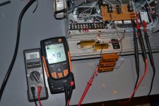
Thank you for the information. If you look at the beige circuitboard over the 4 x 50 uf 500 v polypropylen capacitors, there are 2 red resistors at the right side. They are the 120 ohm between the transformer and rechtifier. the 4 x To 220 right behind them are 4 A hexfreds 600v. The Orange resistor to the left is the 180 ohm you are refering to.
On the left side I have 4 x hexfreds for the -24 v, and the smal ones is for + 30 ( bias for Sreg )
In the center is rechtifier for number 3 heater supply, this is for the phono. This I wil Connect when everything is working.
Today I tryed with some resistors. With 1 k the volt was about 355 and with 2x 1k in paralel ( 500 ohm ) I have about 380 vdc. This is at least inside instruction specificasjon ( minimum 35, and maximum 100 v )
Do you have any input on what to chouse 355v or 380 v ?
This is not a Power amp but could 1k make it a slow power supply ?
Sincerely
Frode
Attachments
Last edited:
Today I tryed with some resistors. With 1 k the volt was about 355 and with 2x 1k in paralel ( 500 ohm ) I have about 380 vdc. This is at least inside instruction specificasjon ( minimum 35, and maximum 100 v )
Do you have any input on what to chouse 355v or 380 v ?
Hi Frode,
I wouldn't worry about fine tuning the PSU voltage quite yet. My strategy at this point would be to leave the series resistor in the PSU as it is, and check the voltage once you have the whole preamp running.
Alex
Hi Frode,
I wouldn't worry about fine tuning the PSU voltage quite yet. My strategy at this point would be to leave the series resistor in the PSU as it is, and check the voltage once you have the whole preamp running.
Alex
Alex !
I am trying to "land" on a in voltage to the Sreg. When I find this voltage, I wil adjust the Sreg to 300 v With the 5k installed between B+ and gnd.
When both Sreg are ok, I will remove the 5 k and install the tubes, and then I was thinking to fintune the 300 volt in the Sreg.
This is at least the plan 🙂 Mayby I missunderstand you.
Sincerely
Frode
Last edited:
Alex !
I am trying to "land" on a in voltage to the Sreg. When I find this voltage, I wil adjust the Sreg to 300 v With the 5k installed between B+ and gnd.
When both Sreg are ok, I will remove the 5 k and install the tubes, and then I was thinking to fintune the 300 volt in the Sreg.
This is at least the plan 🙂
Sincerely
Frode
That sounds like a plan that could get you a working RTP3 in due course...
Alex
Alex !
I am trying to "land" on a in voltage to the Sreg. When I find this voltage, I wil adjust the Sreg to 300 v With the 5k installed between B+ and gnd.
When both Sreg are ok, I will remove the 5 k and install the tubes, and then I was thinking to fintune the 300 volt in the Sreg.
This is at least the plan 🙂 Mayby I missunderstand you.
Sincerely
Frode
The best move in order to check the voltage drop in the raw PS is to load its output (leaving the SRegs out) with the anticipated load of the actual preamp (plus shunt currents in the SRegs). This way, you can check the actual output voltage of the raw PS that will feed the SRegs and fine tune it accordingly in order to get circa 340 V at the input of the SRegs.
Just my 2 cents here.
Regards,
Evangelos
- Home
- Amplifiers
- Tubes / Valves
- Vacuum State RTP3C