You can experiment with different R values using LTSpice. The theoretical voltage values are very close to yours.@Alex M @Joe Rasmussen I removed R5 resistor and measurements are following.
U1 - Pin 1 - R5 removed - 188 V, changing R3 to 1K resistor lower the voltage to 147 V R5 included -
U1 - R3 - Pin 3 - R5 removed - 5,4V - changing R3 to 1K resistor then it is - 3,9 V R5 included
U1 - Pin 6 - R5 removed - 71,6 V - with a R3 resistor changed to 1K resistor then voltage is 152 V R5 included
U1 - Pin 7 - R5 removed - 19,6 V - with a R3 resistor changed to 1K resistor then voltage is 20 V R5 included
U1 - R6 - Pin 8 - R5 removed - 20 V - with a R3 resistor changed to 1K resistor then voltage is 22 V R5 included
U2 - Pin 2 - R5 removed - 148 V with a R3 resistor changed to 1K resistor then voltage is 190 V R5 included
U2 - Pin 3 - R5 removed - 162 V with a R3 resistor changed to 1K resistor then voltage is 197 V R5 included
U2 - Pin 6 - R5 removed - 162 V with a R3 resistor changed to 1K resistor then voltage is 197 V R5 included
U2 - Pin 7 - R5 removed - 0,02 V with a R3 resistor changed to 1K resistor then voltage is 142 V R5 included
U2 - Pin 8 - R5 removed - 72V - with a R3 resistor changed to 1K resistor then voltage is 152 V R5 included
To get U1A pin 1 anode to 100 V then R3 have to be I think about 380 ohms. How to lower the gain then? How that affects sound quality if anode has much higher voltage than 100V?
Ideas how to get this to sound superb?
LTSpice file with phono stage attached. The drawing of the schematic is not very nice but for simple experiments it works 😉 Upper part is an original and with bottom part you can experiment and compare results. If you will change first cathode resistor to 430, then voltage at anode will be about 102V and current 5.9mA. But amplification will increase about 8dB.
Attachments

In the new FVP-6 Line Stage, using the 12AT7, there is a way to control the gain (and reduce noise) that I will reveal. In fact there are two solutions, the best one needs a negative power supply, nice and clean and about minus 10V will to the job.
Having thought about your hint about the extra -10V power supply, I think I understand now. You can use a larger cathode resistance for the same standing current. Have I got it right?
And I would echo your comment about the need for this to be very clean. Do you propose a "mini SuperReg" along the lines of the one in the RTP3?
Alex
@Sarunas is it possible to include ECC88 symbol or 6n23p tube symbol in the LTSpice file? Right now tube symbol is missing.You can experiment with different R values using LTSpice. The theoretical voltage values are very close to yours.
View attachment 1236464
LTSpice file with phono stage attached. The drawing of the schematic is not very nice but for simple experiments it works 😉 Upper part is an original and with bottom part you can experiment and compare results. If you will change first cathode resistor to 430, then voltage at anode will be about 102V and current 5.9mA. But amplification will increase about 8dB.
I played again with FVP5 with the one tube version. I had to change MOSFETS to get it to work. I think the tube uses less current than it should be. With already little bit higher volumes from computer headphone output I get easily distortion. If I lower R3 cathode resistor then pin 1 anode voltage lowers but also pin 3 voltage. If I go lower than 100 V on anode pin 1 I get distortion very easily.
Voltages are
1 - 109 V
2 - 0 V
3 - 2,78 V - to low voltage?
6 - 176 V
7 - 109 V
8 - 110,5 V
U2 - R7 - 11.4 V
U1A - 3,64mA = (201-110)/25k
Joe mentioned that current gets split up, 1.7mA through 47K and rest through gain tube 3,68mA-1,7mA= 1,9mA?
Voltage on R3 = 1,9mA x 2k2 R = 2200*0.0019mA = 4,18 V but I have much less than that.
On this current voltage on R3 does not make sense.
Any ideas? Are the tubes so old and used?
Rename triode_Ayumi.txt to triode_Ayumi.asy and put it in ...\Documents\LTspiceXVII\lib\sym directory, that is a triode symbol file. I have it a little bit deeper: C:\...\Documents\LTspiceXVII\lib\sym\ZZZ\Tubes_Ayumi\
Then rename Triode_Ayumi-Copy.txt to Triode_Ayumi.lib and put it in library directory: C:\...\Documents\LTspiceXVII\lib\sub
If you will open .asy file with any text editor you can find what library it is using. In Triode_Ayumi.lib file is a lot of tube models and you can add more: https://www.diyaudio.com/community/threads/vacuum-tube-spice-models.243950/
Attachments
@Sarunas is it possible to include ECC88 symbol or 6n23p tube symbol in the LTSpice file? Right now tube symbol is missing.
I played again with FVP5 with the one tube version. I had to change MOSFETS to get it to work. I think the tube uses less current than it should be. With already little bit higher volumes from computer headphone output I get easily distortion. If I lower R3 cathode resistor then pin 1 anode voltage lowers but also pin 3 voltage. If I go lower than 100 V on anode pin 1 I get distortion very easily.
Voltages are
1 - 109 V
2 - 0 V
3 - 2,78 V - to low voltage?
6 - 176 V
7 - 109 V
8 - 110,5 V
U2 - R7 - 11.4 V
U1A - 3,64mA = (201-110)/25k
Joe mentioned that current gets split up, 1.7mA through 47K and rest through gain tube 3,68mA-1,7mA= 1,9mA?
Voltage on R3 = 1,9mA x 2k2 R = 2200*0.0019mA = 4,18 V but I have much less than that.
On this current voltage on R3 does not make sense.
Any ideas? Are the tubes so old and used?
View attachment 1238618
I agree that your voltages don't make sense. If V1=109V, the current through the 25K is 5.6mA, which sounds good. But this current through the 2K2 cathode resistor would give V3=12.4V, instead of the 2.78V you report.
I'm suspicious of the voltages V7 and V8 - the cathode should be 4-4.5V positive of the grid.
What voltage do you measure across R7? Measuring the voltages at points 6 and 8 doesn't tell you what the currents through the output stage are.
Alex
Voltage across R7 is 11.40 V and voltage across R3 is still 2,7 V. Voltage on pin 8 is also 110 V.What voltage do you measure across R7? Measuring the voltages at points 6 and 8 doesn't tell you what the currents through the output stage are.
Sorry, among other things a bout of covid at a very inconvenient time. But I haven't forgotten, promise.
I and 3 others I know had the same Xmas present as you! Seems to have run rampant around here last month or so. Luckily this time symptoms were mild.
"Upgrading Vacuum State FVP FVP-5 Tube Line Stage to FVP-6"
Very close to starting the topic, last week been doing quite a bit of preparation. I think you will be able to tell when I post it, that it will be a good and meaty start.
Very close to starting the topic, last week been doing quite a bit of preparation. I think you will be able to tell when I post it, that it will be a good and meaty start.
I decided to do a new layout for the line stage and combine the input selection and stepped attenuator on the same PCB. I haven't had this fabricated yet, but I think it is pretty close. This is a 4-layer board with one layer dedicated to ground planes. 263mm x 190mm.
This PCB is for a single channel and incorporates the following functions:
1) Balanced line stage based on Allen's RTP3D design (although not an exact clone).
2) Op-amp based instrumentation-style line stage for balanced subwoofer output.
3) XLR input and output connections for 3 inputs with relay selection, 1 output from RTP and one for the subwoofer connection. RTP output has a muting relay.
4) Relay-switched stepped attenuator with 128 0.5db steps - 50kohm input impedance per phase.
5) RC/bridge connection to chassis ground.
6) Separate current-mode DC-regulators for each tube.
7) Final stage regulators (using Sparkos discrete regulators) for negative bias supply and op-amp supply.
This board is designed to be used with a separate high-voltage shunt regulator for B+, and with pre-regulated DC supplies for heaters (three separate circuits to elevate heater DC appropriately), negative bias supply for current sources, and bipolar supply for op-amps.
A digital serial bus connects the board to an arduino controller for input selection and stepped-attenuator.
I plan to use VCAP CuTf 1uF coupling caps so this is what the board is laid out to accommodate.
I'll be happy to provide gerber files if there is any interest once I have tested the design, although this will likely be many months in the future since I'm busy with my paying job and have a number of other hobby projects I'm working on in parallel.
The new FVP-6 topic has been spawned:
https://www.diyaudio.com/community/...tube-line-stage-to-fvp-6.407594/#post-7561802
.
https://www.diyaudio.com/community/...tube-line-stage-to-fvp-6.407594/#post-7561802
.
So this will be the second public domain pcb for the rtp3, the earlier one from a French forum is for the rtp3c though.I'll be happy to provide gerber files if there is any interest once I have tested the design
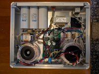
Here, the location of the heat sinks make it impossible to show off the valves via the casework. Not all preamps show off their valves, but the more porn, the more glory!
Just curious whether you are still pursuing your plan for a transistor-based version of the RTP3?The new FVP-6 topic has been spawned:
I don't know for sure that I based this on the RTP3D. The schematics I have don't mention RTP anything anywhere. They are labeled DLT5x88-5A and dated June 26, 2006. The RTP3C schematic that was published on Vacuum State's website has the line-stage labeled as DLT5x88-5 and dated 2000. The schematics I have are clearly a later version with a number of updates, but I can't say for sure this is what was used in the RTP3D.So this will be the second public domain pcb for the rtp3, the earlier one from a French forum is for the rtp3c though.
Here, the location of the heat sinks make it impossible to show off the valves via the casework. Not all preamps show off their valves, but the more porn, the more glory!
That said, my implementation is not a clone of this design anyway. I used the same topology and mostly the same values, but my current source design is completely different. I am using cascoded NPN transistors with LM385 voltage references. I am also connecting the grids on the bottom triode in the cathode follower to ground and using a negative bias on the CCS, similar to the RTP3C design.
I'm also using individual voltage regulators for each tube's heater, and have set these up as current regulators (i.e., regulating the current to deliver 6.3V across the filament), with a separate trim-pot adjustment for each tube. This approach is what Allen recommended in his Tube Preamp Cookbook, although it seems as if later RTP implementations used a simpler design.
If you have the cookbook you will have the RTP3D schematic.Tube Preamp Cookbook
I have the 2nd edition which appears to have content up to 1998 so I think this just had early RTP3C info (as well as discussions about the RTP4 and 5 which are simplified versions).
Just curious whether you are still pursuing your plan for a transistor-based version of the RTP3?
Good question, but this is problematic as I am having commercial interest to consider. The power amplifier design I have needs a fully balanced line stage and the similarities are too great. I do have to make a living, as you can understand, so how far I can go on the DIY front is sometimes problematic. I am not saying that I won't, just not at this stage.
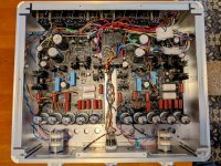
This took me about a year. Probably the most complicated build so far.
I got the PCBs and the information on how to build from @Algar_emi
This was a very difficult build and @Algar_emi helped along the build. I also had help from my dear friend @Sarunas
RTP3 sounds awesome, happy on how it turned out. I didnt have a chance to test the balanced input/output, this is the next step.
@Algar_emi has many other audio projects, PM him and ask what he has, he is a great guy. I am a NOOB and had a lot a patience with me.
Attachments

- Home
- Amplifiers
- Tubes / Valves
- Vacuum State RTP3C