Last week's snow was the largest single day total since I moved here 7 years ago. It was not a normal snowfall. So far, the cheap single stage thrower does Ok on a day's accumulation. This week It rained steadily for two days, then the temps dropped below freezing. The freezing rain, sleet, and frozen crud fall started late yesterday afternoon. Sometime overnight it started snowing and has not stopped. Attempts to shovel through the frozen stuff have failed. Nobody has yet attempted to traverse our frozen dirt road either. There was no mail delivery yesterday, and no mail or garbage pickup today. I don't plan on trying to go anywhere until it thaws which may not be until Sunday.
I was in Rochester Minnesota during the blizzard of 78. You guys have far more white stuff than us.
I was in Rochester Minnesota during the blizzard of 78. You guys have far more white stuff than us.
It is good to know that the 8068 works and sounds good. I have a bag full of used tubes that were pulled from water damaged Kepco power supplies that went to the metal scrapper when I moved out of Florida. They are on my list of tubes to try as is the 6BH6.
It will be interesting to find out if the 5.7 watt heater in the 8068 costs more in plate efficiency than it saves in heater power VS the 15.75 watt heater in the 6CD6, or 6CB5 or 25DN6. I would like to build a high efficiency SE amp someday using the principles I learned in cellular transmitters at Motorola. It's basically a class G or H design, but the output device stays in class A, or class AB in the LTE transmitter since the distortion was fixed with DSP magic (predistortion).
Unfortunately, little has been done in the lab for some time. Today will be spent shoveling snow and ice or doing taxes. As of yesterday morning about a third of this county had no power, many roads were impassable due to ice, and snow continued to fall all day yesterday. Church service for this morning was cancelled yesterday due to lack of power and an ice covered parking lot. At least the sun is shining, and the temperature is expected to rise above freezing for the first time in 5 days. It's 14 degrees F (-10C) right now though.
Attachments
From Electronics-Tutorials.ws: "Class G Amplifier – Class G offers enhancements to the basic class AB amplifier design. Class G uses multiple power supply rails of various voltages and automatically switches between these supply rails as the input signal changes. This constant switching reduces the average power consumption, and therefore power loss caused by wasted heat."
From Learnabout-Electroncs.org: "Class H improves on class G by continually varying the supply voltage at any time where the audio signal exceeds a particular threshold level. The power supply voltage tracks the peak level of the signal to be only slightly higher than the instantaneous value of the audio wave, returning to its lower level once the signal peak value falls below the threshold level again. Both classes G and H therefore require considerably more complex power supplies, which adds to the cost of implementing these features."
Well, as usual, in the course of normal conversation you open up the vista. I had never even heard of these two classes and aside from the bits quoted above there is precious little detail in a simple Google search for mere mortals. Sounds interesting though. Do these classes use chips that require computing/firmware to run?
Take care of those 8068's. I was shocked to see what people are asking for them now. Yeah, nice tubes and all but . . . . . .
PS. It's a bit weird that some days it's warmer here than 3000 klicks farther south. Not what you'd think is normal. Friends in TX are wearing long-johns and socks to bed while I wake up too hot from two thin wool blankets and the heat is turned off. One-offs have been happening forever (The ones I remember most from newspaper pics are the heavy frosts in Florida orange groves and smudge pots in rows to protect the trees) but sustained weather over weeks is a recent thing as far as I know.
Carver's M-400 "Magnetic Field Amplifier" was one of the early class H designs. No processor or software involved, just three sets of supply rails and some logic to switch between them. I have seen class H done with and without processors and software for both audio and RF applications. There were many class G and H solid state amps around for a time before class D became dominant in the race for BIG power.From Electronics-Tutorials.ws: "Class G Amplifier – Class G offers enhancements to the basic class AB amplifier design. Class G uses multiple power supply rails of various voltages and automatically switches between these supply rails as the input signal changes. This constant switching reduces the average power consumption, and therefore power loss caused by wasted heat."
From Learnabout-Electroncs.org: "Class H improves on class G by continually varying the supply voltage at any time where the audio signal exceeds a particular threshold level. The power supply voltage tracks the peak level of the signal to be only slightly higher than the instantaneous value of the audio wave, returning to its lower level once the signal peak value falls below the threshold level again. Both classes G and H therefore require considerably more complex power supplies, which adds to the cost of implementing these features."
Well, as usual, in the course of normal conversation you open up the vista. I had never even heard of these two classes and aside from the bits quoted above there is precious little detail in a simple Google search for mere mortals. Sounds interesting though. Do these classes use chips that require computing/firmware to run?
Take care of those 8068's. I was shocked to see what people are asking for them now. Yeah, nice tubes and all but . . . . . .
PS. It's a bit weird that some days it's warmer here than 3000 klicks farther south. Not what you'd think is normal. Friends in TX are wearing long-johns and socks to bed while I wake up too hot from two thin wool blankets and the heat is turned off. One-offs have been happening forever (The ones I remember most from newspaper pics are the heavy frosts in Florida orange groves and smudge pots in rows to protect the trees) but sustained weather over weeks is a recent thing as far as I know.
Nearly 15 years ago Circuit Cellar magazine and Microchip ran a design contest to generate interest in the then new dsPIC chips, a 16 bit PIC with DSP features. I used that chip to create an agile power supply for a class H SE tube amp using the same concepts that I had pioneered for a SE mosfet RF power amp at 700 MHz. The original RF hardware was all discrete, no processor involved. The contest required the use of a dsPIC chip and was centered around demonstrating one or more of its unique features. What could be more unique than a vacuum tube audio amp being controlled by a dsPIC? I designed and built such a beast and submitted it to the contest where it won the "best use of SMPS features" prize. That get me some cash and a magazine article published. In reality the SMPS and A/D hardware in the dsPIC does all the hard work. The code only initializes the hardware and does some simple math.
The article itself generated little interest except for a few phone calls, a discussion, and a job offer from Hartley Peavey. Mention of the concepts here drew little interest, and a good bit of that was negative, or just "why?" I had many other things to do, so this never got explored further and the amp itself was stripped for parts and discarded when I had to move out of Florida. The article is included in case you are interested.
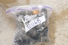
I have a high school friend who is still a surplus dealer in Florida. I used to help him test and repair surplus electronics in exchange for stuff I could use. One day there was a semi-trailer full of electronics that had been left outdoors in the Florida weather for months. There were lots of power supplies, some still full of water. I got an HP6448B (0 to 650V @1.7 A) that was quite rusty inside but worked after applying about half a can of WD40. I still use it for big power experiments. There were several of those old 200 watt Kepco supplies that use the 8068. I managed to play musical parts and get one of each kind working, which I used for several years and eventually sold. Many had no tubes, broken tubes, or severely corroded tubes stuck in their sockets. The tubes in the bag were the survivors from that operation. Each worked in a live power supply but may or may not be good enough for audio. NOS 8068's do go for stupid money but used ones that look like mine are still cheap on Ebay.
Most cold fronts that move through Florida do last for a day or two. I can remember a few that lingered for more than a week. When frost appeared on the car windows in Miami (rare) the standard treatment was to wash it off with the garden hose. I remember being in the 7th grade and it being too cold to ride my bicycle to school, so mom told me to wash down the car (a 1953 Dodge) and start it. When I turned on the hose no water came out and when I picked it up it broke in half. It was hard frozen. It stayed around freezing for about a week. That would have been in 1964/65. One year in the 1990's I was up here in West Virgina for the winter and for a week it was warmer here than it was in Florida. The orange, strawberry, and tomato crops were all a total loss that year. There were a few other really cold events that lasted a week or more, but most are generally short lived.
Attachments
"Mention of the concepts here drew little interest, and a good bit of that was negative,"
I understand the purist analoguer thinking that a non-linear supply is against the spirit of analogue , ( even if it's mostly because we don't really need to know much to bias and power a tube so we can make ourselves look like we know what we're doing if we just deny all the harder stuff on philosophical grounds) but with Class A tube amps being as inefficient as they are it makes a lot of sense to me to claw back some efficiency where you can.
The stopping point in my world is when it gets to code. I don't know any programming languages . I tried Python for Arduino but I used it so seldom that I'd have to start from scratch every time I wanted to do something. For that reason I thought that Cypress' PSoC was pretty attractive , with its on screen drag and drop icon programming of both digital and analog modules within a single chip. It looked pretty friendly for my style of doing stuff so I picked up what they called an Eval board - at the time taking it for a completely reprogrammable chip with all the needed hardware support on board. I didn't realize until I got it that it just had fixed and very limited functions ( like light up an LED after a timed delay) that couldn't be altered . They just ran when you powered up and hit start. Pretty dull. It would have been just as interesting to watch it on TV . . . . . . . . . . And to get farther in , a significant investment of time and money needed to follow.
Anyway, That's why I asked about software in the G and H classes. I wouldn't get into it if I have to write code or depend on another who either might or might not be around to help if the chip forgot who it was. I'll certainly read your article though. I can't remember ever seeing anything you've written that wasn't interesting (and often entertaining in a pyrotechnic sort of way. : ) Thanks for posting it .
Yes, there are 5 left and I will likely use a couple for experiments and testing. I probably will not order any more until I have learned all there is to know about this one.George, do you have any more beta boards available?
When you are given over 100,000 tubes for free you use just about anything to store them. I had three 55 gallon drums full, lots of boxes, and bags and some plastic totes, all stuffed with tubes. At one time I had three 10 X 20 foot warehouse bays full of tubes. It took about 6 years to sort, then sell, trade, give away, and even trash some of them. I'm down to about 5,000 now (best guess) after moving everything 1200 miles.I'm extremely interested to see where your experiments lead. And I'm also comforted to see I'm not the only one who squirrels away tubes in Ziploc bags.
I had to chuckle a little bit because my situation was similar but on a much, much smaller scale. People have been giving me tubes for 20 years now, and I've accumulated two or three thousand myself.
Two weeks ago I went into the basement to retrieve some tubes out of my stash, only to discover several of the plastic tubs partially filled with water. That area flooded during a thunderstorm late last year and apparently those containers (they were the ones with the hinged flaps for lids) were right beneath the "waterfall". You can imagine the mess - I've been drying and re-sorting tubes ever since. Oddly, they don't seem any worse for wear; all the ones I've tested several in circuits so far seem to be fine. Apparently I rescued them before pin corrosion became a problem.
I just never realized how many 6AL5s, 6AU6s, and 12AU7s I really had! Geez...
Last edited:
I just completed another UNSET pcb build this time wired for 26HU5 tubes. Changes from the BOM include
R113/R213 33K
R108/R208 100K
B+ is 350V
110mA on the output tubes (~30 watts calculated)
Driver tubes are the same 12GH7A I have been using and of course a pair of 26HU5s for the output. I am seeing 0.35% THD at 1W and 14.5W at 5% THD.
R113/R213 33K
R108/R208 100K
B+ is 350V
110mA on the output tubes (~30 watts calculated)
Driver tubes are the same 12GH7A I have been using and of course a pair of 26HU5s for the output. I am seeing 0.35% THD at 1W and 14.5W at 5% THD.
Hi spiggs,
Great results! Does the 0.35% THD at 1W coincide with the best sound subjectively? With your 6DQ5 build I remember you liked the sound better when THD was a slightly higher than the minimum you could achieve.
I’m back from my Florida winter hiatus now and hope to get back to my UNSET amplifier building. Unfortunately I don’t have any 26HU5s. So, I will rethink if I want to continue with my 6DQ5 build, or go for the “big one” with 26LW6s, of which I have several pairs.
I have not had a chance to do an extended listening session with the 26HU5s but the 0.35% THD was measured with a 2H dominant harmonic profile very similar to my preferred profile when using the 6DQ5s. Like with the 6DQ5 I can adjust it lower. First listening impressions are good but I'll really pump some music through it this weekend and see.
Side note for Beta builders. In this build I used multi turn adjustment pots again but with the 3 pins inline and drilled a hole through the pcb to accomodate the middle pin. Soldered pin 1 and 3 in and used a short extension to connect the wiper pin on the underside. Made for a neater and more secure install than I have on the other board.
Side note for Beta builders. In this build I used multi turn adjustment pots again but with the 3 pins inline and drilled a hole through the pcb to accomodate the middle pin. Soldered pin 1 and 3 in and used a short extension to connect the wiper pin on the underside. Made for a neater and more secure install than I have on the other board.
There are two size bottles for the GE 26LW6, skinny and fat. Many of the fat ones have additional heat radiating wings attached to the plate for an increase in plate dissipation capability. The skinny 26LW6 is nearly identical to the 26HU5 in construction and can be used interchangeably with the 26HU5 in the UNSET board and most other applications. I favor the 26HU5 because I have a lot of them, and I got them for under $10 each. I can swap back and forth between the 26HU5 and the 26LW6 with only a bias adjustment.. Unfortunately I don’t have any 26HU5s. So, I will rethink if I want to continue with my 6DQ5 build, or go for the “big one” with 26LW6s, of which I have several pairs.
I have some 6DQ5 that are in the same size bottle as my 26HU5 tubes. Most 6DQ5 bottles are shorter though but not by much. Of course the 26HU5 has a lot more plate in it. Is the 26LW6 rated at 40W? Do you think the 26HU5 is conservatively rated at 33W being so similar? I have been running them at around 30W so far.
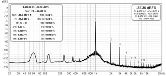
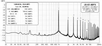
Attached are graphs of my 26HU5 UNSET at 1W 0.34% THD and just a bit over 5% at 14.5W. Gave it a good listen this weekend and it sounds much like the 6DQ5 setup which is good. I also decided to measure my SSE for comparison. The SSE is setup in triode mode with EL34 tubes. At 1W it had 1.8% THD and 5% came at 5W. Heavily 2H dominant all the way up to 5W. What does the TSE measure like with a 300b?
Attached are graphs of my 26HU5 UNSET at 1W 0.34% THD and just a bit over 5% at 14.5W. Gave it a good listen this weekend and it sounds much like the 6DQ5 setup which is good. I also decided to measure my SSE for comparison. The SSE is setup in triode mode with EL34 tubes. At 1W it had 1.8% THD and 5% came at 5W. Heavily 2H dominant all the way up to 5W. What does the TSE measure like with a 300b?
Attachments
The original spec sent to JEDEC in 1971 BY GE for the type number registration for the 6LW6 shows a fat 1.75 inch T-14 bottle and a plate with an "integral fin and radiator anode design" for "great power handling." It is rated for 40 watts of plate dissipation. An addendum to this filing was added in 1972 to include the 26LW6. The only change is to add a 26 volt 600 mA heater variant. All early "LW6's had fat bottles. I have seen 3 or 4 different variations of the heat radiating fins on GE 'LW6's, and some fat bottles with no fins.
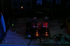
Sylvania began making 'LW6's sometime later in 1.5 inch bottles without the fins on the plates. GE followed suit sometime in the 70's. I don't know exactly when the 26HU5 appeared as I was working at Motorola by then and most of my projects were silicon based. The spec for the 26HU5 that I have is from an RCA tube manual, but I have never seen an RCA branded 26LW6 or 26HU5 that was actually made by RCA. All are made by either Sylvania or GE. The 26HU5 is rated for 33 watts. The later Sylvania made tubes have little winglets on the ends of the plates. The early ones do not. The amount of dissipation that these tubes will eat is highly dependent on how well they were built. Both of these Lindal branded GE "fat bottle with no fins" 36LW6's are eating 65 watts. One is more red-faced than the other.
I have not measured a TSE or TSE-II with a 300B in many years. Much of my experimentation with the TSE-II was done with the 2A3 as this is one of the hardest tubes to tame in many amps, and all my 300b's are 15+ year old Sovteks or Shuguang's. Most of my experiments were done well above the published ratings too. Who runs a 2A3 on 375 volts at 80 mA? My 15 year old Shuguang's see no signs of distress at this level and have been in the amp for nearly two years.
I found that the OPT and the idle current will make a huge difference in the amount of 3rd harmonic being produced several years ago. It is possible to drop the 3H down into the noise with some OPT's (notably the $29 Edcor) at 1 KHz just by playing with the bias current. I saw near zero 3H at about 80 mA with the small Edcor at 1KHz. This vanished as the frequency was changed. I have seen the 3H "null" in some other OPT's but not to this level. Either it doesn't exist in the large Edcors, or I haven't found it. Listening tests don't show much change as I ran a 300B from 70 to 90 mA through the little Edcors since we don't tend to listen to 1 KHz sine waves, and real speakers are not 8 ohm resistors.
Attachments
Last edited:
Attached are graphs of my 26HU5 UNSET at 1W 0.34% THD and just a bit over 5% at 14.5W. Gave it a good listen this weekend and it sounds much like the 6DQ5 setup which is good.
spiggs,
Thanks again for your informative posts and experimentations. Your 4.6% result on third harmonics at 14.5 watts got me thinking again about the driver current.
Why would that be, I’m wondering. I don’t know much about how higher order distortion is increased at increased power, but does it have anything to do with running the drivers at near starvation plate currents in the BETA UNSET?
For your latest version with 12GN7/26HU5 and B+350v, if you have a chance could you please measure the current through your 12gn7 drivers again, as well as the supply voltage at the top of the load resistor?
Back in October 2021 I also wondered whether higher current through the drivers would decrease distortion. George reply is below.
In the Beta board design the plate supply is used for the drivers too, but could a seperate higher voltage supply to the drivers be the solution? This should not be a problem as far as I can see. (Must the control grid via R106, 206 now be derived from the the higher driver supply?).
George, if you think this is a worthwhile line of investigation, could you to dust off the LTSpice sim to check out what a higher driver supply would achieve?
I have tried nearly every driver tube that will fit the socket. Yes, most of them could benefit from more current, but more current without changing other parts means lower plate voltage. The plate voltage is already pretty low, and lowering it further brings some tubes into their non linear region.
Lowering the plate resistor value brings the voltage back up, but reduces the gain.
To increase the current one could simply turn up the bias current which reduces the cathode voltage. This also reduces the input headroom for the driver mosfet. To increase the headroom the control grid voltage on the tube must be increased by changing the grid voltage divider resistors.
At the point I released the schematic and BOM all of the component values were taken from the LT Spice simulation which was done with a 6EJ7 and a 6DQ5. Are they optimum for every possible tube combination? No. Are they even optimum for a 6EJ7 and a 6DQ5? Probably not, but some serious tinkering with a box full of resistors hasn't found much better yet.
I have ventured of into a side road with a CCS across the plate load resistor to increase the current without lowering the load impedance, but haven't drawn any good conclusions there either. I did see some really high power output numbers by driving the output tube right out of pure class A and using feedback to keep the THD under 3%. I'm not going further down this road until I have the FFT box set up.
Measured across R7 I see 348V and 305V so about 6.3mA total current in this setup. I have been thinking the same, that the driver tubes can use more current which is why I decreased the value of R108/208 and one of the reasons I wanted to try bigger output tubes and more bias current. Interestingly one other test I did was to lower the plate voltage way down on the driver tubes with the thought that this is another way to get more current. At 1W around 60V 3H becomes dominant but then around 50V 2H comes back up. Setup like this 2H remains slightly dominant all the way to clipping. However if I adjust both channels to 50V the amp becomes unstable somewhere around 5-6W.spiggs,
Thanks again for your informative posts and experimentations. Your 4.6% result on third harmonics at 14.5 watts got me thinking again about the driver current.
Why would that be, I’m wondering. I don’t know much about how higher order distortion is increased at increased power, but does it have anything to do with running the drivers at near starvation plate currents in the BETA UNSET?
For your latest version with 12GN7/26HU5 and B+350v, if you have a chance could you please measure the current through your 12gn7 drivers again, as well as the supply voltage at the top of the load resistor?
Back in October 2021 I also wondered whether higher current through the drivers would decrease distortion. George reply is below.
In the Beta board design the plate supply is used for the drivers too, but could a seperate higher voltage supply to the drivers be the solution? This should not be a problem as far as I can see. (Must the control grid via R106, 206 now be derived from the the higher driver supply?).
George, if you think this is a worthwhile line of investigation, could you to dust off the LTSpice sim to check out what a higher driver supply would achieve?
Just a little more playing around with the 26HU5 UNSET this evening. Increased the B+ to 400V to see what it would do. Adjusted bias to 100mA to keep the tubes within spec. 1W performance much the same at 0.35% THD and 5% THD pushes up to 17W. I also tried hooking the 4 ohm taps to the 8 ohm dummy load for a 6000K output load. 1W distortion dropped down to 0.2% THD and 5% THD came at 11W.
- Home
- More Vendors...
- Tubelab
- UNSET Beta Board Build