Still hunting for some info Output -formers
I'am in doubt, what difference the two OPT's will be in real life situ?
The one's i was looking for is claimed to be for 300B's :
TTG-KT88SE - Tube output UL transformer [3kOhm] KT88 / 300B SE
Intended for Single Ended
Core type Toroidal
Ultralinear tap 43%
Nominal Power 40W
Nominal anode current 250mA
Frequency bandwidth (-3dB) 10 Hz - 56 kHz
Secondary Impedance 4 and 8 Ω
Primary Impedance 3,0 kΩ
Turns Ratio (Np:Ns) 27,39:1 (4Ω) , 19,36:1 (8Ω)
Primary Inductance Lp 39,5 H
Primary Leakage Inductance Lsp 10,88 mH
Total Primary DC Resistance 85,4 Ω
Effective Primary Capacitance 7,6 nF
The One's OldHector is using are claimed to be :
TTG-EL34SE - Tube output UL transformer [3,2kOhm] EL34 / 6L6 SE
Intended for Single Ended
Core type Toroidal
Ultralinear tap 43%
Nominal Power 40W
Nominal anode current 100mA
Frequency bandwidth (-3dB) 10 Hz - 56 kHz
Secondary Impedance 4 and 8 Ω
Primary Impedance 3,2 kΩ
Turns Ratio (Np:Ns) 28,28:1 (4Ω) , 20,00:1 (8Ω)
Primary Inductance Lp 51,2 H
Primary Leakage Inductance Lsp 0,73 mH
Total Primary DC Resistance 112 Ω
Effective Primary Capacitance 11,2 nF
I'am pretty sure the smaller EL34 version will work in this amp, but why they are claiming it to be for EL34 / 6L6 and not mention 300B etc.. Or is there something i'am not aware of?
The price difference between them are not much, so it does not matter much (within 12$)
I really hope someone can help me answering this as i am in doubt.
Rgds; Jesper.
PS. : USPS updated the shipping information of my TSE pcb to being on it's way from Copenhagen now
The question on the Torodiy output transformers seems general enough that you might also get some information in the "Tubes" forum. I searched there for "Toroidy 300B" and got a few threads including this one that may be of interest (I didn't read the whole thing)
Problem - SE Class A with toroidal OT ?
Chas
Problem - SE Class A with toroidal OT ?
Chas
Thanks all.
I had a conversation with OldHector, which is using the small 100mA OPT.
They seem to work very good, and do not get hot or some.
He asked a quistion simulair to mine some time ago, which was cleverly answered by George (It was a quistion about some other transformer) :
Also i see, that the bigger 250mA OPT, has ~20% less inductance, excatly as George described it above.
I did read a lot of stuff about this, all kind's of old stuff regarding anode current / OPT / turns ratio etc..., but it was not clear for me, that choosing a smaller OPT could actually work better (thanks Csample for kicking me in the right direction)
Thanks all.
Jesper.
I had a conversation with OldHector, which is using the small 100mA OPT.
They seem to work very good, and do not get hot or some.
He asked a quistion simulair to mine some time ago, which was cleverly answered by George (It was a quistion about some other transformer) :
The transformer you listed is optimized for use at 120 mA. This means that the gap in the core (required for SE operation) is a bit wider than the same transformer optimized for 90 mA. As seen in their data, the inductance drops a bit because of the wider core gap. Other than the slight loss in inductance, it will work fine at all currents up to the maximum rating of 210 mA, but it will work best at 120 mA. The loss of inductance may make a small difference in bass response especially when a small tube is being used to drive it. The 6L6 types would be the worse case, followed by the EL34. A 6550, KT88 or 300B should work just fine with this transformer.
Also i see, that the bigger 250mA OPT, has ~20% less inductance, excatly as George described it above.
I did read a lot of stuff about this, all kind's of old stuff regarding anode current / OPT / turns ratio etc..., but it was not clear for me, that choosing a smaller OPT could actually work better (thanks Csample for kicking me in the right direction)
Thanks all.
Jesper.
Nice Richart; which amp are you using, how much output power?
...
Rgds; Jesper.
SSE, with Telefunken EL34's scrounged from an early 60's Dynacord guitar amp. Not sure what the output power would be - 20% efficiency, and 50W dissipation, so around 10W?
Thanks again all
So can you guy's tell me if my final quote will be appropriate ?
Power transformer ::
325 - 0 – 325V (250mA)
5V (3A)
3,15 - 0 - 3,15V (5A)
Output transformers ::
Intended for Single Ended
Core type Toroidal
Ultralinear tap 43%
Nominal Power 40W
Nominal anode current 100mA
Frequency bandwidth (-3dB) 10 Hz - 56 kHz
Secondary Impedance 4 and 8 Ω
Primary Impedance 3,2 kΩ
Turns Ratio (Np:Ns) 28,28:1 (4Ω) , 20,00:1 (8Ω)
Primary Inductance Lp 51,2 H
Primary Leakage Inductance Lsp 0,73 mH
Total Primary DC Resistance 112 Ω
Effective Primary Capacitance 11,2 nF
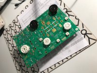
I populated my board... And only thing i miss now is the 300B's & the transformers (most expensive parts through)
Looking forward to hear some eventually comments about my choice of toroids for this amp!?
As i wrote before, i asked them, and the toroids have air-gabs, for stopping the DC flowing.
Rgds; Jesper.
So can you guy's tell me if my final quote will be appropriate ?
Power transformer ::
325 - 0 – 325V (250mA)
5V (3A)
3,15 - 0 - 3,15V (5A)
Output transformers ::
Intended for Single Ended
Core type Toroidal
Ultralinear tap 43%
Nominal Power 40W
Nominal anode current 100mA
Frequency bandwidth (-3dB) 10 Hz - 56 kHz
Secondary Impedance 4 and 8 Ω
Primary Impedance 3,2 kΩ
Turns Ratio (Np:Ns) 28,28:1 (4Ω) , 20,00:1 (8Ω)
Primary Inductance Lp 51,2 H
Primary Leakage Inductance Lsp 0,73 mH
Total Primary DC Resistance 112 Ω
Effective Primary Capacitance 11,2 nF
I populated my board... And only thing i miss now is the 300B's & the transformers (most expensive parts through
)Looking forward to hear some eventually comments about my choice of toroids for this amp!?
As i wrote before, i asked them, and the toroids have air-gabs, for stopping the DC flowing.
Rgds; Jesper.
Attachments
Hi All,
I realize now that I'm starting that I ordered a 5W part for R6, not the 6.5W that is recommended. This is for a 300b TSE-II build. Should I source the 6.5W part or do you think I'm okay as is?
I ordered the 5W part from the parts list (P/N CW00510K00JE73) and it is marked for 6.5W.
If you need to reorder, George mentioned that a chassis mounted resistor could be used for the 300B. You can read about it in this thread: TSE-II Heat Sinks This allows D6 to stay at 150V and keeps heat out of the mosfets. I removed the 6.5W R36 from my board and replaced it with a chassis mount that is rated to dissipate 14W without mounting to a heatsink and 50W when mounted to a heatsink. Overkill, but it was the same price as the smaller chassis mounted resistors ~ $3. The resistor I am using is Ohmite P/N HS5010KJ if you are interested in this route.
Oh you're right -- I looked close and the bag they came in says 5W but it's a 6.5 part. Problem solved - thanks!
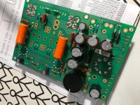
So I finished building my tseii board last night. Thanks George for the quick shipping!
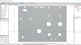
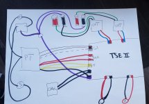
I just had a question for everyone on my layout before I placed my order for the top plate. I attached a photo of the layout Im planning on using and was hoping for some feedback on any potential issues caused by placing everything on the top plate. Power transformer, choke and power switch are on the left side. Power plug and fuse are above PT. My main concerns are the orientation btw the PT and choke and the proximity of the OT to the binding posts. DO either of these things have the potential to cause issues? Thanks
Bryce
Attachments
So I finished building my tseii board last night. Thanks George for the quick shipping!
I just had a question for everyone on my layout before I placed my order for the top plate. I attached a photo of the layout Im planning on using and was hoping for some feedback on any potential issues caused by placing everything on the top plate. Power transformer, choke and power switch are on the left side. Power plug and fuse are above PT. My main concerns are the orientation btw the PT and choke and the proximity of the OT to the binding posts. DO either of these things have the potential to cause issues? Thanks
Bryce
Hi Bryce,
I am not able to see the mounting holes for the choke on the layout you posted. I don't know of any issue with the location of the binding posts relative to the output transformers. A couple things I saw were the output transformers look maybe a little close to the power tubes, and I didn't see access holes for adjusting the potentiometers. Some slots/holes located over the hot areas on the board could help (over devices with heatsinks and large resistors). Lastly, I don't know what the rest of your case looks like, but some of the holes near the back edge (binding posts, fuse ...) could interfere with a rear wall on the case.
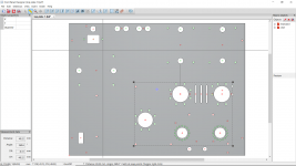
Thanks for the feedback. I made a few changes and posted the current plan.
The choke holes are on the bottom left corner situated vertically. I added some vent holes between the output tubes in order to get some fresh air to R36, which is supposed to get pretty hot. I was able to push the PCB forward a little bit which gives me about 2" between the tubes and the OPT. The access holes are there, just kind of small and hard to make out. The game plan is to assemble everything on this top plate and drop it on top of a wooden frame. I will cut a small ledge into the top inside edge of the wood for the plate to sit on.
Is there any other places on the board where I should put some additional vent holes/slots?
Thanks again for the feedback, this is my first build that isn't from a kit and its been quite the learning experience.
Attachments
Transformer Wiring Question
I am using an Edcor XPWR247 for my power transformer and it has dual outputs for both the 5V and 6.3V heater taps. I plan to wire these in parallel to create one output of each voltage. I have checked each set to insure that when connected in parallel they will be in phase. Is there anything else to check? Are there any problems with doing this?
Thanks and Merry Christmas!
Chas
Attachments
Thanks for the feedback. I made a few changes and posted the current plan.
The choke holes are on the bottom left corner situated vertically. I added some vent holes between the output tubes in order to get some fresh air to R36, which is supposed to get pretty hot. I was able to push the PCB forward a little bit which gives me about 2" between the tubes and the OPT. The access holes are there, just kind of small and hard to make out. The game plan is to assemble everything on this top plate and drop it on top of a wooden frame. I will cut a small ledge into the top inside edge of the wood for the plate to sit on.
Is there any other places on the board where I should put some additional vent holes/slots?
Thanks again for the feedback, this is my first build that isn't from a kit and its been quite the learning experience.
The overall layout looks good. The PCB holes look very similar to mine, hopefully you saved some time and used mine as a template.
Some questions/notes:
- Which tubes are you using? 300B dissipate more heat than 45's ....
- Seems like you won't use a volume pot? If yes, make sure there is enough space in the front to put it.
- The 2 holes in front seem like they are for RCA sockets? They may be a bit close if not soldering directly to the board.
- 90deg between OPT and PT look good. I did find that it helps reduce noise when they are on the same axis and not off-axis as in your layout. This probably also depends on the particular PT you're using.
- Consider an IEC switch with built-in fuse, it will save space on top.
- When using a wooden base, I generally like putting everything on top as you did. In this case though, it should be easy enough to drill 4 round holes in the rear panel right behind the OPT's for the binding posts. I think that would reduce some wire clutter when everything is hooked up.
Best of luck! I am also finishing up a second TSE now and am at the chassis phase
I am using an Edcor XPWR247 for my power transformer and it has dual outputs for both the 5V and 6.3V heater taps. I plan to wire these in parallel to create one output of each voltage. I have checked each set to insure that when connected in parallel they will be in phase. Is there anything else to check? Are there any problems with doing this?
Thanks and Merry Christmas!
Chas
I'm pretty much a novice so take this with a grain of salt.
With the secondaries hooked in parallel, they will be rated at:
6.3V @ 8A and 5V @ 8A.
A 300B build needs no more than 4A (each 300B takes 1.25A) for the 6.3V tap and and 3A for the 5V tap.
I believe hooking in parallel will result in more heat being dissipated by the regulators.
I think I would just cover the ends of the extra taps wrap aside.
Thanks for taking a look and offering some feedback.The overall layout looks good. The PCB holes look very similar to mine, hopefully you saved some time and used mine as a template.
Some questions/notes:
- Which tubes are you using? 300B dissipate more heat than 45's ....
- Seems like you won't use a volume pot? If yes, make sure there is enough space in the front to put it.
- The 2 holes in front seem like they are for RCA sockets? They may be a bit close if not soldering directly to the board.
- 90deg between OPT and PT look good. I did find that it helps reduce noise when they are on the same axis and not off-axis as in your layout. This probably also depends on the particular PT you're using.
- Consider an IEC switch with built-in fuse, it will save space on top.
- When using a wooden base, I generally like putting everything on top as you did. In this case though, it should be easy enough to drill 4 round holes in the rear panel right behind the OPT's for the binding posts. I think that would reduce some wire clutter when everything is hooked up.
Best of luck! I am also finishing up a second TSE now and am at the chassis phase
I did steal the PCB layout from your posting. Thanks for making it available! Saved me lots of time not having to do it myself.
I am going to be running 300b and no volume pot. Im currently feeding my amps from the pre-outs on my avr so Im able to use it for volume control. The rcas are at the front of chassis and are indeed pretty close to both the edge of the board and the edge of the chassis. I couldn't think of anywhere better to put them and space got tight after pushing the board as far forward as possible to make space btw the tubes and OPT. The fused IEC is a great idea. Ill probably order one right now and make the adjustments to the plate.
I'm pretty much a novice so take this with a grain of salt.
With the secondaries hooked in parallel, they will be rated at:
6.3V @ 8A and 5V @ 8A.
A 300B build needs no more than 4A (each 300B takes 1.25A) for the 6.3V tap and and 3A for the 5V tap.
I believe hooking in parallel will result in more heat being dissipated by the regulators.
I think I would just cover the ends of the extra taps wrap aside.
Bringing the windings parallel just makes the xformer capable of delivering more current, the regulators don't care.
Rest is correct
Jesper.
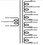
tse ii wiring plan
so this is my current wiring diagram. Transformer wire colors should be correct for UBT-2 OPT and xpwr-178 power transformer. Anyone see any issues with the plan? Please ignore my less than stellar drawing skills.
Bryce
so this is my current wiring diagram. Transformer wire colors should be correct for UBT-2 OPT and xpwr-178 power transformer. Anyone see any issues with the plan? Please ignore my less than stellar drawing skills.
Bryce
Attachments
Last edited:
so this is my current wiring diagram. Transformer wire colors should be correct for UBT-2 OPT and xpwr-178 power transformer. Anyone see any issues with the plan? Please ignore my less than stellar drawing skills.
Bryce
The fuse and the switch should both be on the hot lead. The fuse should be as close to the hot inlet as possible, an IEC inlet with built in fuse is nice for this.
The fuse and the switch should both be on the hot lead. The fuse should be as close to the hot inlet as possible, an IEC inlet with built in fuse is nice for this.
so wire should go.... iec-fuse-switch-pt-iec ?
- Home
- More Vendors...
- Tubelab
- After a 14 year run, the TSE must DIE!