Read through the white papers on the Hartley site. They mention a "magnetic" suspension they worked out in the 1950's along with a number of other interesting ideas.
Thanks Demian. Very informative white papers.
Almost all these interesting ideas were a subject of an issued patent. Check out “Luth, Harold J.”
I had heard a 10inch FR Hartley of such a construction and it was really good sounding
George
Attachments
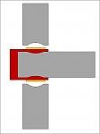
yes. That is cookie-cut from thin fiberglass sheet.... very stiff. The cone edge surround is rubber/cloth.... very flex.
Both have same affect as to tug on the VC/cone and cause distortion.
THx-RNMarsh
back in the day (1970-80-ish ?) ---- this is the Hartley Demian is talking about.....I had a stereo pair of the 18 inchers in a rear loaded folded transmission line (See Speaker Builder). measured flat to 16Hz in my room. At one time I laid them on their side and sat the original QUAD ESL on them... made the ESL about ear height.
I am not sure how well the magnetic suspension idea worked... didnt see any harmonic tests at that time. But , i think Ferro-fluid has replaced this idea.

Hartley 218 drivers as subs for a custom built DynAudio 3-way (W-M-T-M-W).
When I did not need them...I gave them to my brother-in-Law who used them on stage in northern California clubs ... he is obviously a bass player. he loved the sound but not moving them. Each the size and weight of a refrigerator.
THx-RNMarsh
Last edited:
But , i think Ferro-fluid has replaced this idea.
It’s not the same concept.
Ferrofluid is concentrated along the width of the front plate and stays focused there.
It doesn’t move with the voice coil like the iron particles which are glued on the voice coil in the patent of Harold Luth.
Therefore with ferrofluid, the flux flow isn’t moving along with the voice coil.
Subsequently ferrofluid can not provide any magnetic restoration force.
George
You could make a spider like the one above out of phosphor-bronze or beryllium-copper and use it for lead out connections as well.
Hi, If memory serves, Ted Jordan used that idea in his speakers.
/örjan
^ From here http://www.ejjordan.co.uk/PDFs/EJJ_1966.11_WW_titanium.pdf
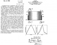
"One very important requirement for the suspension system is that it must be completely linear over the full range of cone displacement. Failure to be so results in the very high harmonic distortion apparent in the extreme bass response of many loudspeakers. The suspension system itself must be mechanically stable, and this requirement led to the use c,f three tangentially disposed beryllium copper cantilevers (two of which are used to carry the voice coil current). The cantilevers are attached at their inner ends to a rigid insulating annulus surrounding the coil and attached to the coil via a " lossy " compliant medium the purpose of which is to ensure that the mass of the suspension system is decoupled from the coil at high frequencies. "
"One very important requirement for the suspension system is that it must be completely linear over the full range of cone displacement. Failure to be so results in the very high harmonic distortion apparent in the extreme bass response of many loudspeakers. The suspension system itself must be mechanically stable, and this requirement led to the use c,f three tangentially disposed beryllium copper cantilevers (two of which are used to carry the voice coil current). The cantilevers are attached at their inner ends to a rigid insulating annulus surrounding the coil and attached to the coil via a " lossy " compliant medium the purpose of which is to ensure that the mass of the suspension system is decoupled from the coil at high frequencies. "
It’s not the same concept.
George
Yes, it is not the exact Same.
Depending on where Ferro-Fluid is placed, it seems to lower distortion. How does it do that?
Anyway, I like my idea with shaped pole piece, better. Less added weight to VC. plus several other bennies.
Attachments
Last edited:
Appart magnetic changes, as I understand, the ferrofluid dump the displacement of the moving coil.Depending on where Ferro-Fluid is placed, it seems to lower distortion. How does it do that?
(The effect is obvious looking at the Waterfall curves)
It is more or less proportional to the speed. So harmonics are reduced more than fundamentals ?
Anyway, if ferrofluid seems to be a good idea, i believe it is not. It tend to dry with age and heat and always finish to glue the moving coil.
Last edited:
And meanwhile, here's where the mainstream audio market is going..?
C200 | Portable | Loudspeaker Systems | Behringer | Categories | MUSIC Tribe
C200 | Portable | Loudspeaker Systems | Behringer | Categories | MUSIC Tribe
3dB, I would say?
So, i wasn´t _completely_ mistaken then....
")
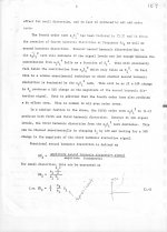
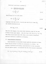
But in fact, under the assumptions that the system under test is still working in a weakly non linear fashion and the excitation frequencies are close together (so additional frequency dependent effects can be neglected) then from using a Taylor series for approximation of the transfer function it follows that HD2 = 0.5 x IM2 (frequency of IM2 = f2 - f1)
Of course it is an idealized description of the system and real life measurements will diverge a bit, but it shows that the two tone difference frequency measurement is suitable to give a fairly accurate figure for the HD2 number.
Last edited:
So, i wasn´t _completely_ mistaken then....
But in fact, under the assumptions that the system under test is still working in a weakly non linear fashion and the excitation frequencies are close together (so additional frequency dependent effects can be neglected) then from using a Taylor series for approximation of the transfer function it follows that HD2 = 0.5 x IM2 (frequency of IM2 = f2 - f1)
Of course it is an idealized description of the system and real life measurements will diverge a bit, but it shows that the two tone difference frequency measurement is suitable to give a fairly accurate figure for the HD2 number.
And what about finding H3 from that test?
THx-RNMarsh
And what about finding H3 from that test?
The Taylor series keeps on going.
Can you derive enough info on the transfer function from an IM measurement to predict the specifics of its harmonic generation? Especially when its very linear to start with?
if so I'll start playing with IM measurements on microphones next week. John Curl now has mike preamps and can so some limited stuff with his microphones.
if so I'll start playing with IM measurements on microphones next week. John Curl now has mike preamps and can so some limited stuff with his microphones.
- Status
- Not open for further replies.
- Home
- Member Areas
- The Lounge
- John Curl's Blowtorch preamplifier part III