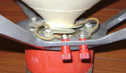
This is the Hartley spider that a variation is still in use (or so they claim). its a spring. NOW AVAILABLE
Most speakers rely on the surround to limit the travel, not the spider.it can be another source of distortion, both from radiation and nonlinear flex.
Most speakers rely on the surround to limit the travel, not the spider.it can be another source of distortion, both from radiation and nonlinear flex.
Attachments
This is the Hartley spider that a variation is still in use (or so they claim). its a spring. NOW AVAILABLE
Most speakers rely on the surround to limit the travel, not the spider.it can be another source of distortion, both from radiation and nonlinear flex.
yes. That is cookie-cut from thin fiberglass sheet.... very stiff. The cone edge surround is rubber/cloth.... very flex.
Both have same affect as to tug on the VC/cone and cause distortion.
THx-RNMarsh
Thanks Keantoken for this book you linked. It is truly remarkable in its practicability and detail for most speaker problems. I hope that everyone interested will look at it carefully.
You could make a spider like the one above out of phosphor-bronze or beryllium-copper and use it for lead out connections as well.
Read through the white papers on the Hartley site. They mention a "magnetic" suspension they worked out in the 1950's along with a number of other interesting ideas.
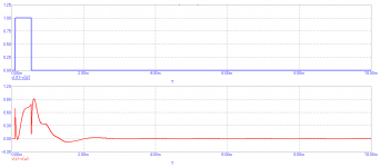
PMA, I hope you realize that I was being polite. '-) What I see is a 3 way speaker with the tweeter leading, with a midrange out of phase, lagging by about 0.5ms, then the woofer coming in sometime. I cannot make a direct comparison, because the usual measurement is a step response that has more low frequency information, so far as I can tell.
Is it the fact that you used a pulse rather than a step and how relatively 'clean' it graphs?
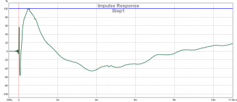
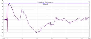
It is a 2-way speaker, in fact. Those time responses are difficult to interpret correctly and even more difficult to get any correlation between visual shape and listening impression. What we call "time lagging" is in fact a phase information of the allpass cross-over circuit. Impulse response is more useful than a popular step response. We need to get a proper phase from the drivers to prevent dips and suck out of the frequency response, that would lead to strong sound coloration. It is the electrical signal from the cross-over that creates visual time lag. The step response is as it is and is a secondary product, not a primary goal.
I used the impulse of finite length to get some energy, a single sample impulse produces low SPL amplitude. I posted the time record intentionally, because the popular interpretation is often incorrect, IMO, and should not be a primary goal in a speaker design, separately from frequency responses and directionality pattern.
Attachments
You cannot compensate any spider/suspension nonlinearity with the motor because this only works way below resonance (spring-loaded region of operation), a region that is seldom used in a practical speaker. Above resonance (mass-loaded), spider/suspension have no influence on distortion and a "compensated" motor would just add extra distortion.
Excatly. Point in case. The step (or any other time-domain) response contains no other information than the total phase (and magnitude) response. By looking at it in isolation, it is absolute impossible to see how many drivers are involved and how the XO is setup, if any drivers are inverted etc. I always have a healthy laugh when I see how people try read things from a step response that just aren't there (and quite often they are wrong, myths and dangerous half-knowledge are spread this way), even the "professional" reviewers in Stereophile etc are prone to this guessing. For me it is clear indicator that they have no clue about speakers from a systems theory standpoint.It is a 2-way speaker, in fact. Those time responses are difficult to interpret correctly
You cannot compensate any spider/suspension nonlinearity with the motor because this only works way below resonance (spring-loaded region of operation), a region that is seldom used in a practical speaker. Above resonance (mass-loaded), spider/suspension have no influence on distortion and a "compensated" motor would just add extra distortion.
Really?
here is how and where all distortions are generated --->
https://www.klippel.de/fileadmin/_m...linearities–Causes_Parameters_Symptoms_01.pdf
THx-RNMarsh
Sure. See section 6.1, for example. It immediately follows from first principles.Really?
The excursion seen by the coil is the same excursion that is seen by the suspension, so it should be possible to compensate a certain amount of the distortion with the motor, but only within a certain frequency range, and only where nonlinear compliance causes distortion in the first place, and only distortions that are in phase with the displacement.
I did finally learn why the BL(x) distortion charts did not show reducing distortion with frequency:
So they used a pilot tone and simply didn't mention it in all but this one whitepaper. 🙄
Table 5 shows typical IMD and AMD responses measured by using the alternative sweeping
technique where the bass tone is at f1 = 10 Hz but the voice tone is varied in the audio band.
Since Bl(x) produces amplitude modulation both measures give identical values. Both values are
also independent of the frequency because the fixed bass tone provides constant peak
displacement.
So they used a pilot tone and simply didn't mention it in all but this one whitepaper. 🙄
Electrostatic transducers are limited by the gap. At high frequencies they van be quite efficient and have high output. A 100 Hz high pass filter in front of Quads can get significantly more out before clamping.
And by that same token, large excursions (through larger gaps, natch) can be traded off against voltage sensitivity (but not a linear conversion), and higher voltage sensitivity requires higher transformer turns ratios. Fortuitously, larger gaps reduce loading capacitance, so electrostatic woofers with dedicated transformers *could* be done.
It's good to see someone write about electrostats' efficiency. Too often folks conflate conversion efficiency with a combination of sensitivity and the reactive load of parasitic capacitance.
All good fortune,
Chris
even the "professional" reviewers in Stereophile etc are prone to this guessing. For me it is clear indicator that they have no clue about speakers from a systems theory standpoint.
Absolutely. You are reading my mind 😉.

The excursion seen by the coil is the same excursion that is seen by the suspension, so it should be possible to compensate a certain amount of the distortion with the motor,
yep. One small improvement step at a time.
driver dependant But I wonder how much could be improved.
THx-RNMarsh
Last edited:
- Status
- Not open for further replies.
- Home
- Member Areas
- The Lounge
- John Curl's Blowtorch preamplifier part III