I know someone who passed his amateur license test Saturday, and is wondering if he's going to find his call letters on the FCC site before they shut down. I took my test on a Saturday and found AK4XL on the site the next Monday evening, but that wasn't over a holiday weekend and I've heard they're not as fast as that now.
My grandfather loaded a couple of pals and my self into his Lincoln Continental, with the suicide doors, and drove us down to Little Rock to sit for our General exams before the traveling FCC man. Seems like the tickets showed up in the mail five or six weeks later.
He was a pre WW1 radio guy, never got on the air again after the ban was lifted, but considered getting an amateur radio license to be one of life's rite of passages in order to become a well rounded young man. He passed a few years after I got my ticket; I wish I had taken the opportunity to learn more about the early history and the characters that shaped it, from someone who likely knew most of them.
Win W5JAG
I had a tech license in 1965 -- and graduated to General a few years later, after stumbling on the code part of the exam (and all I did thereafter was either code, or screw around on 2 meters trying to make things work.)
It took about 6 weeks for the ticket to arrive.
I still have the Eico 735 of the era.
It took about 6 weeks for the ticket to arrive.
I still have the Eico 735 of the era.
Getting better.
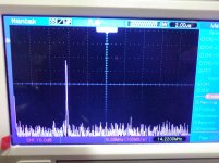
The 9 MHz IF is 34 dB down. The tunable LO is all but banished. The sum product is 28 dB down.
Need to take a little capacitance off the tuned circuit. This is with the FeelTech as a signal generator.
Hopefully tomorrow I can try out the Si5351 synthesizer again.
Win W5JAG
The 9 MHz IF is 34 dB down. The tunable LO is all but banished. The sum product is 28 dB down.
Need to take a little capacitance off the tuned circuit. This is with the FeelTech as a signal generator.
Hopefully tomorrow I can try out the Si5351 synthesizer again.
Win W5JAG
Attachments
This is with the Si5351 spur maker.
No balance or bandpass filtering on the output - just raw single ended output through a .01 cap at pin 4. 100 mv on the RF port to simulate the SG-9; 250 mv on the tunable LO port. 7 volts on the SA612.
The small spike out at 39 MHz is the sum of that really undesirable spur that would have been too close in to the 14 MHz output and the tunable LO. I think, the arithmetic looks right ...
Win W5JAG
Attachments
I had a tech license in 1965 -- and graduated to General a few years later
I had learned much of my early tube knowledge from a ham radio operator who lived nearby. He was the older brother of one of my class mates. He got me interested in Ham radio, and I already had two Hallicrafters receivers in my growing radio collection.
I got a surplus ARC 5 transmitter still in it's cloth covered packaging at a surplus store near my house. I built the necessary power supply from old TV parts and got a couple of 40 meter crystals from the ham guy. I could light up a 40 watt incandescent bulb with 7 MHz RF.
Months of studying from real books and code practice with a bent spoon and DIY oscillator, and I was ready for the Novice test. Back then (early 60's) you had to visit the local FCC field office, by appointment, if there was one within 50 miles. It was at the federal building in downtown Miami, not a place I had ever been near.
On the scheduled day my father was too hung over from the previous nights football game, so the trip didn't happen. This scenario happened once or twice again, and my early ham radio dreams were gone. The ARC 5 eventually morphed into a guitar amp, that I could do on my own.
I had been attending the Miami hamfest and other local hamfests since the early 70's primarily for the flea markets. I began selling at those shows with some friends and co-workers in the mid 70's. The ham club at work offered novice license classes and administered the tests, so sometime in the late 70's or early 80's I became a licensed novice ham.
One day in the mid 80's my friends were selling at a hamfest. It was raining very heavily, and there was virtually nobody present. My self and a friend both had our novice licenses, and the announcer came over the speakers stating that license tests would be administered in about 2 hours. We bought a Technician study guide and did a one hour cram course with that book. Two hours later we took the test, and we passed. I was now a tech class ham. When the code requirement was dropped my tech license became a "tech plus." The "tech plus" license went away sometime in the late 90's and my latest paper license just said "tech."
Sometime in the 2000's I decided to upgrade my license. The official policy of the ARRL (and therefore most VEC's) at the time was that a paper copy of a "tech plus" license was required for an automatic upgrade to General.....I did not have my original 80's vintage tech plus paper. I had tossed it when the renewal license came in the 90's.....
Several discussions with all the local ham clubs that had VEC's were fruitless. Sometime in the mid 2000's the ARRL changed it's stance. If your call sign appeared in an ORIGINAL official paper call book with the words "tech plus" next to it, you could receive an automatic upgrade to General. Surely someone out there had an 80's vintage paper call book, maybe I could even find one at a hamfest or on Ebay. I called all the local ham clubs again, but came up empty.
A year or so later I found my call sign in an online directory with the words "tech plus," would this be OK? One ham club about 20 miles away said that they would send an email to the ARRL to ask for clarification on the matter.
About a week later I get a phone call from that ham club. They had not heard back from the ARRL, but one of their members had an old paper call book with my call sign and the words "tech plus." If I came to their testing session in a few days, and paid the $17 filing fee, I could upgrade to general.....OK, if I have to pay the fee, can I take the extra class test and receive an extra if I pass, or a general if I don't? They would have to check on it, but assured me that nobody could pass that test without some serious study.
I got a phone call back the next day stating that I could indeed take a shot at the extra test, and wished me luck. A few days later, I became the first "no code extra" that they had seen. I still have my novice call sign though.
Here is a bit of an odd result.
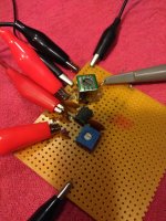
Si5351 / SA612, same operating points as before, except the load is a surplus 1000 micro henry slug tuned, shielded coil, The intent was to tie the two output pins together for balance, and create a balanced broadband output of sorts, and take the output from the secondary of the transformer.
The coil has pins for a secondary, but in fact, as I learned by accident, they are just there for mounting purposes - there is no secondary ...
First pic is the scope lead attached to pin 4 of the SA602 - no coupling cap.
Second pic - wait for it - is an accidental short of the can to the output pin 4 of the SA612, creating, I guess, some kind of low value gimmick capacitor between the can and the unconnected output pin that the scope probe was attached to, making an 18 dB, across the board, attenuator.
Which makes for a pretty decent looking output ... except it doesn't balance out the 9 MHz input ...
Win W5JAG
Attachments
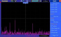
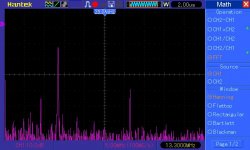
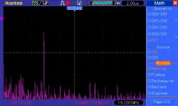
This is the current Si5351 / SA612 combination - the LO and the spurs from the Si5351 are down in the FFT noise. The 9 MHz IF is either down in the noise, or a few dB above it - hard to tell.
The output from the SA612 is being taken single ended to a single tuned circuit; the scope probe is on the secondary of the transformer. The accidental creation of the gimmick output suggested that much lighter coupling out of the SA612 could be beneficial, and, in these grabs, a 100 pf disk isolates the tuned circuit from the mixer output. Previously I had been using .01 uF. Lighter coupling might yield additional improvement.
I had thought about using MC1496, but this result with SA612 is better than I expected, dirt simple, looks to be adequate to my untrained eye, and, given the way this has dragged on, and the now obsolete status of MC1496, I don't think I'm going to play with it.
I think there is still some additional benefit to be had from a second tuned circuit on the output, so may play around some with that, then play around with that cheap linear amp, to see if it is really linear, and if I need any additional drive for it.
As always, comments, criticisms, and suggestions on how to proceed are welcomed.
Win W5JAG
Attachments
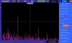
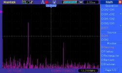
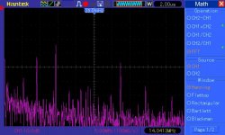
Si5351 / SA612 tx mixer output; double tuned bandpass, top coupled, stagger tuned to +- 1 dB across the phone band.
The junk around 5-7 MHz is, I think, phantom FFT artifacts.The signal around 32 MHz is the IF plus the LO. The signal around 11 MHZ, if real, is a mix product with one of the spurs, I think.
Win W5JAG
The junk around 5-7 MHz is, I think, phantom FFT artifacts.The signal around 32 MHz is the IF plus the LO. The signal around 11 MHZ, if real, is a mix product with one of the spurs, I think.
Win W5JAG
Attachments
Thought about this some; haven't worked on it much.
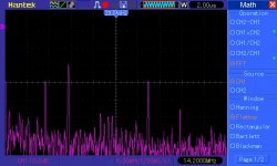
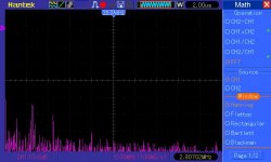
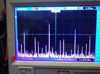
That junk around 6 MHz has concerned me because that 15 - 16 MHz spur beats with the 9 MHz IF, to put a difference frequency in that region. And it won't get any more filtering because every thing after the bandpass will be a low pass filter.
I took an FFT of just the SA612 with 6 volts B+ applied, but both the oscillators turned off, and it still shows junk in the 6 MHz region. I don't know what is going on with the FFT here, but these are not beat frequencies being shown. That FFT is pic 1. FFT 2 is the same conditions, both oscillators turned on. If I mentally subtract pic 1 from pic 2, this seems like a pretty decent output, especially considering the starting point. The signals at 32 MHz ish ( IF + LO ) and 39 MHz ish ( spur + LO ) are real, but already down around the bottom of the FFT dynamic range, and will be subject to further low pass filtering, so I'm not concerned with them.
So, I think I am going to move on to hooking up the little "linear" amp and start connecting things together with some T/R switching and control circuitry. I don't know anything about SWR protection, so I guess I will have to learn about that, hopefully not the hard way. Suggestions are welcomed.
For speech compression, I have some ancient LM370 and will try one in the TX audio chain after everything else is done. AN LM370 might also be an easy squelch circuit for RX - I've never played with them. Like everything else in the LM37X series, it seems to have never really caught on. I think the Hallicrafters FPM 300 used it - can't think of any other commercial application. It's in the early 1970's era databooks - I found a first page of the datasheet online, and it is attached.
As an aside, playing around with the SA612 balance control trick, on this example, best LO balance occurs right around the point of maximum current draw into the SA612, so for someone wanting to try this trick without access to an FFT, that will get you pretty close. LO Balance also varies as B+ varies, so regulation is important, and if B+ changes, balance should be checked and possibly reset. Ambient temperature does not appear to materially affect balance. When balanced, I haven't found any material difference between 5 and 8 volts B+ on the SA612 output spectrum, so use whatever is convenient. This trick appears to work really well; the Si5351 would be unusable without it. Or just really dirty.
Win W5JAG
Attachments
Starting to see a light at the end of the long tunnel.
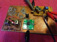
A few more tweaks and putting the TX mixer over a proper ground plane cleaned it up considerably. It is now at the limits of my mediocre test equipment. It is much better than I expected to get, considering how nasty the Si5351 looks straight out of the chip, and considering that the TX mixer is really an RX mixer. This should be a clean sounding transmitter if it works in the real world like it does on the bench ...
I added an SMA connector to the mixer board output, to make building out the rest of the TX strip more convenient.
I am going to do up all the switching, case it, and start real world testing of the prototype. Not sure about the linear yet, but I still have quite some work to do before that is an issue.
If this works in the real world, and when I get there, now that I (sort of) know what I am doing and what works, a 6 meter transverter will follow, and should be easy ...
Then maybe a new IF board better suited to an up converting front end.
Win W5JAG
Attachments
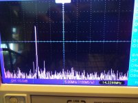
Yes, the SA602/612 looks to be getting the job done here, with a really simple, ham DIY friendly circuit.
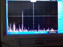
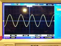
Just out of need to know, I flipped the LO around to use a 5 MHz low side injection to get to 14 MHz, and attached pics of the LO input to the mixer, and the spectrum at the output of the bandpass filter. Sorry, I left the jump drive at the office so cheap cell phone pics are all I have.
The 5.23 MHz LO FFT is centered at 6.26 MHz, the output FFT is at 25 MHz ish.
I did not rebalance the mixer, so some improvement is likely possible. Regardless, even though low side injection is clearly not as good as high side injection, the output still looks usable - the two close in spurs are almost 40 dB down.
Win W5JAG
Attachments
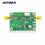
Is this a linear amp?
This is a picture of the RF output board, from the eBay listing. The part I received is identical. It is described as an "Amplifier Type: A class of linear amplification" and linear is used more than once in the ad copy.
eBay ads can be somewhat fast and loose with the truth, which I have no problem with for cheap stuff, but I'm wondering if this is one of those instances, or if there is something I don't understand.
I don't see any bias to the first transistor, so it seems to me that can only be class C operation? On the board I received, I cannot make out any part numbers on the transistors. I thought that would be handy to know when I blow them up playing with it. ( edit: could it be a chip with an internal bias network? Do such parts exist? ) The other three terminal part is a 78L05.
What looks like a pi attenuator on the input, is not wired as such on mine. It has two 51 ohm resistors to ground with a zero ohm resistor in between, so this seems like a 25 ohm input?
I think it likely I will actually need to substitute the correct parts for an attenuator if I use both stages; I'm wondering now if I should just remove the input transistor and replace it with a zero ohm jumper, and just use that last stage, which does look like it could be class A. I have about 0.6 volts p-p coming out of the mixer.
Win W5JAG
Attachments
Last edited:
could it be a chip with an internal bias network? Do such parts exist?
yes, there are hundreds of different kinds and the SOT 89 package is quite common for them.
The devices are probably not simple transistors. They are most likely 50 ohm gain blocks and are probably not identical. The first one is probably internally biased and probably provides most of the gain while the second handles the power and probably has somewhere near 10 db of gain.
Any numbers / symbols at all on the parts?
Well it can't be class C, with RF that works only over a narrow band of frequencies and needs a tuned circuit.
Perhaps there are other layers on the PCB with connections we can't see...
Why not apply 12v and measure the voltages on the transistors to see?
Even more radical: "stuff" some RF in and see what happens.
Perhaps there are other layers on the PCB with connections we can't see...
Why not apply 12v and measure the voltages on the transistors to see?
Even more radical: "stuff" some RF in and see what happens.
- Home
- Member Areas
- The Lounge
- No RF gear here?