That is how I understood your posts, too.
I may have interpreted the "faulty" into it, if so, sorry.
Although neither I would install a dc-blocking board that allows the DC to fry the speaker before coming in action.
I am asking myself (and everyone knowing more) wether this might be corrected with some magic part (no idea, the piece that gets the board to react...)
I think the weak point is the relay... It takes time to go from one state to another. That time might be more than a speaker can handle. Like I said, I ran a couple test and was not satisfied with the result.
Relay speed
I will try the modification suggested by Rod Elliot in his article on relays. I will add the zener diode in series with the coil diode. I have already wired the relay contacts as suggested in his project 33. He also suggests not to use miniature relays as the contacts are too close together, which is why I went off board with the relays.
I will try the modification suggested by Rod Elliot in his article on relays. I will add the zener diode in series with the coil diode. I have already wired the relay contacts as suggested in his project 33. He also suggests not to use miniature relays as the contacts are too close together, which is why I went off board with the relays.
Attachments
Good morning and happy 21 everyone!
I would like to ask for toecutter (the board designer?), jason (the store-„manager“?), or some other person involved in this project to drop into this discussion.
Thompsontech says this board does not work as intended, and I am far from capable to verify this. My gut-feeling tells me that it would be strange that a faulty project exists/survives/is sold some 8 years, but on the other hand this very thread seems to be a bit abandoned...
@thompsontech, I am not questioning your knowledge, but could it be that a hardware-bug creeped in while you were struggling with the faulty bom and availability-issues? This is the question I would inquire the mods to examine and to verify wether the board indeed is doomed or not...
Thank you!
David


Hi David,
One of the mods alerted me to this discussion.
As things have grown, I've spread myself pretty thin across the forum, the store, and manufacturing of existing and new parts kits and complete kits. One of the areas that has suffered is me being across forum discussions. The store has now grown to a point where I need to appoint resources to stay abreast of these discussions, ensure all the BOMs are maintained, all the links work, and proactively engage, get feedback, and update the product range. At the moment everything is being done on a reactionary basis, which isn't great.
The goods news is that over the past month a lot of progress has been made on engaging good help to assist with all these challenges, and I'm going to start making some public announcements in the new couple of weeks to let everyone know what's going to be happening over the coming months to upgrade and revitalize every area of the forum and the store.
Regards this board, and its performance...
The speaker protection board was designed by a respected diyAudio forum member, many years ago. I am not an EE or qualified to comment on the circuit, but I am pretty sure that it was based on a published, established circuit by an esteemed designer.
Over the last ~8 years I don't recall ever hearing of someone suggesting the board doesn't work. Quite the contrary, many have given feedback that it works very well.
If Thomsontec has found the board is not working correctly, and assuming he's used all the exact parts specified in the latest BOM (V3.0.2), I would ask that he provide the full details of the use application so we can huddle with the designer and work out why it isn't working for him as intended.
Thompsontech says this board does not work as intended, and I am far from capable to verify this. My gut-feeling tells me that it would be strange that a faulty project exists/survives/is sold some 8 years, but on the other hand this very thread seems to be a bit abandoned...
As mentioned, my time has been spread thin and I rely on feedback. If a part in the BOM becomes obsolete (as they always do), please send in a new BOM and I can upload it. Over the years, there have been a few updates to various BOMs, and they have been updated and uploaded to try to keep them current. However I think the whole process could be improved with the appointment of a chief-of-BOMs, an clearly published BOM update suggestion form/process, or an adopt-a-BOM kind of project. All great ideas, just need the time to implement them and make them canon.
we have a diy product in the store, that offers limited/no protection
This is a big statement to made, and not the feedback I've received over the years at all. Many have commended the design. But I'm very happy to dig deeper into this.
Right now I'm on holiday and not able to give this as much attention as I'd like until the 2nd week of January, but I'll start shooting out some emails as soon as you reply with a detailed description of your test environment, what you expected to happen, and what you observed happening.
For the love of God please update the BOM on page 1! Six years and it still hasn't gotten done.
I know there are version, but just dump the PDF version 3 off there please.
What's worse is I caught it ordered the right ones then put the damned wrong one in. GAHHARRRR!
The latest version is 3.0.2, which is what is linked there. I have just done a little bit of housekeeping to ensure all the links work and that the only remaining version is 3.0.2. If you (or anyone) would like to send me a list of updates, notes, tips, etc, that should go in the BOM, I'll have the designer make the updates and publish an updated BOM.
EDIT: I resaved the 3.0.2 BOM as 3.0.2b with a focus on the latest 3.0.2 BOM being on the first sheet, and that first sheet will appear when the XLS is opened. The old BOM is now in a subsequent sheet in the XLS.
Last edited:

Damn transistors KSC945 has two pinouts I saw that highlighted back in the build in the first two pages I ordered the darn transistors which I thought were correct per the bom and it hasn’t been changed to reflect the proper ksc 945 without the “C”. That caused a lot of hassle now I need to remove them and see if I can order the correct ones ! Please correct the bom please it is a shame that I can build all the other store products without issue but this simple circuit is causing all people trouble because of poor documentation!😡
Sorry for any confusion. The current version of the BOM which has been unchanged for many years, 3.0.2, lists Mouser 512-KSC945YTA for Q1/2/3/5/6.
I have just uploaded a new XLS file (3.0.2b), which puts the 3.0.2 BOM on the first sheet of the XLS to avoid any confusion, and linked to this from both the first post of this thread as well as the product page. The old V3.0 PDF has been removed entirely.
When we updated the XLS from 3.0.0 to 3.0.2, the "BOM History" sheet in the XLS was added to help avoid any confusion and show a clear change history in the BOM, in this case documenting "Transistor changed from 512-KSC945CGBU to 512-KSC945YTA".
However it appears that leaving the old 3.0 PDF was an oversight, especially considering the update was a correction not a substitution - my apologies. In future we'll ensure that old BOMs are thoroughly scrubbed, and also scan the thread history and annotate any posts with incorrect information (I've added scanning and updating this thread to the todo list).
Last edited:
Hi David,
One of the mods alerted me to this discussion.
Good morning Jason, and happy new year!
Thanks very much for jumping in and clarifying things.
I was the one who sounded the alarm. Becuase there were some people with troubles, and who got disappointed with the board. Since I couldn‘t imagine a faulty project would be in the store for so long, but not able to get it clarified on my own (i haven‘t even connected my board yet, and wouldn’t be able to debug it if it had a fault) ... but I‘d like to confirm that the thread is a bit confusing, with even 6l6 being forced to make corrections and the error „still not clarified“ (or just hard to figure it out)...
Since the speaker protection is next on my list, I am next in the line to confirm (or not) the functionality...
I don't have any faith in the board, when I did the test per the instructions it took a second or so to disconnect.... a second and the speaker is toast. I'm now looking for another solution.
I'll be honest here, this is the first time I've seen and looked at this circuit...
Just looking at this and simulating it and it seems to work very well. The delays are all text book R/C intervals and I have to say it behaves as expected.
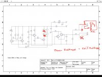
This is the circuit I came across... is this what you are using?
Also shown is the relay delay which gives about 10 seconds from power first appearing until the relay closes.
When a DC offset occurs the relay opens in around 160 milliseconds. That delay is entirely under user control and can be varied by altering the time constant of the input filter.
When the fault condition is removed the relay reconnects again after the 10 second delay.
The behaviour was the same for negative going offsets.
The .asc file is attached.
Attachments

Wow, thank you, Mooly, for thoroughly looking into it. Your examination confirms my belief: diyaudiostore and the folks behind are trustworthy 🙂 and it will be up to me to get there...
(Just don’t know how to express myself better)
(Just don’t know how to express myself better)
When a DC offset occurs the relay opens in around 160 milliseconds. That delay is entirely under user control and can be varied by altering the time constant of the input filter.
Thank you for your comments Mooly and Happy New Year to you!
Which components are you referring to which control the DC offset delay in the circuit and is trying to make it a shorter timeframe create more issues it’s worth? Is 160ms a reasonable shutoff time to protect a speaker?
Mostly all the pages in this thread have dealt with powering the relays (cause they’re easy to test for functionality) but there hasn’t been any reasonable discussion about the DC protection part of the circuit (until recently where that poor chap lost his one speaker).
Cheers, Pete
Thanks you Mooly, that is a great test.When a DC offset occurs the relay opens in around 160 milliseconds.
The behaviour was the same for negative going offsets.
The .asc file is attached.
Could you confirm @ which Dc values + and - the relays disengage for your test.
Thanks Jason,However it appears that leaving the old 3.0 PDF was an oversight, especially considering the update was a correction not a substitution - my apologies. In future we'll ensure that old BOMs are thoroughly scrubbed, and also scan the thread history and annotate any posts with incorrect information (I've added scanning and updating this thread to the todo list).
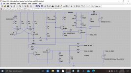
The schematic is not updated Post#1. Look @ Post 293
Wow, thank you, Mooly, for thoroughly looking into it. Your examination confirms my belief: diyaudiostore and the folks behind are trustworthy 🙂 and it will be up to me to get there...
(Just don’t know how to express myself better)
You're very welcome 🙂 and thanks.
Thank you for your comments Mooly and Happy New Year to you!
Which components are you referring to which control the DC offset delay in the circuit and is trying to make it a shorter timeframe create more issues it’s worth? Is 160ms a reasonable shutoff time to protect a speaker?
Mostly all the pages in this thread have dealt with powering the relays (cause they’re easy to test for functionality) but there hasn’t been any reasonable discussion about the DC protection part of the circuit (until recently where that poor chap lost his one speaker).
Cheers, Pete
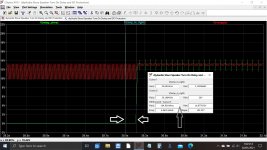
The time taken for the circuit trip is determined by the voltage on R11 exceeding - or + 0.7 volts approximately. When that happens either Q4 or Q5 will turn on (depending on offset polarity) and turn the relays off.
So the factors effecting this are the time constant of the two 330uF caps and the 27k feeding them.
If the time constant is made to small then the circuit will trip on wanted high voltage bass notes. So it is a compromise (as all these type of circuits are, it is not unique to this one).
So the 330uF caps can be reduced and that will decrease the trip time. I would not recommend increasing the 27k's because these are needed to allow sufficient base current for the trip transistors to be available in the event of a true fault.
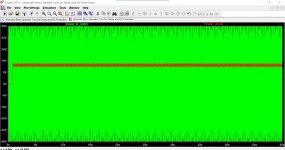
Fitting 100uF caps for example now gives a trip time of just over 60 milliseconds.
Given that we normally listen to just a few volts in output there is no harm in reducing these caps if you feel you want faster protection.
The simulation can also be used to apply a low frequency input voltage and so allow a determination of when the circuit might trip. High frequencies are filtered by the R/C time constant, it is the bass that is the problem.
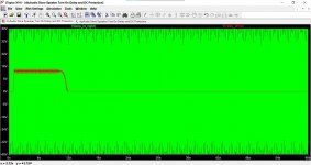
Lets try 20Hz at 40 volts peak. So that is the nominal 50 watts rms/8 ohm value. And it seems fine with just 100uF caps fitted. You can see the relay trace in red.
Lets go to 47uF. And that shows the circuit now will not close the relay. The signal itself is tripping the circuit... but that is 50 watts worth of signal at 20Hz.
So I would by all means experiment. The worst that can happen is the relay trips when you turn up the volume and there is lots of bass.
And Happy New Year folks

Attachments
Thanks you Mooly, that is a great test.
Could you confirm @ which Dc values + and - the relays disengage for your test.
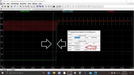
So here is the circuit when faced with a slowly rising DC offset.
The relay connects after 10 seconds and then the amplifier develops a rising offset.
You can see the trip point is around 3 volts DC. That value is higher than the 0.7 volts or so that some might have expected because of the potential divider action of the 27k and the 10k.
That actually throws up the question of what happens when a fault is present in just one channel. This means the good channel is still at zero volts and so the 27k of that channel will also effectively appear in parallel to the 10k.
The effect of that is to slightly raise the trip voltage a little higher, however these values still give very low power dissipation in the speaker during that time if such a fault as a low DC offset appeared.
For example 3 volts DC is just over 1 watt dissipation in the bass driver unit.
Attachments

So I would by all means experiment. The worst that can happen is the relay trips when you turn up the volume and there is lots of bass.
Thank you Mooly!
Pete
To test it's dc-protection, I would just apply a battery to one of it's speaker-connection, is that correct?
I managed to get it running, it lights up and the relays close after 3 or so seconds. But I'm not sure how to check for DC-detection—nothing happens after connecting a battery between spk1 / in 1...
I managed to get it running, it lights up and the relays close after 3 or so seconds. But I'm not sure how to check for DC-detection—nothing happens after connecting a battery between spk1 / in 1...
It should trip when more than around 3 to 3.5 volts of either polarity is present on one of the inputs.
The initial delay should be more than 3 seconds.
The initial delay should be more than 3 seconds.
- Home
- The diyAudio Store
- Speaker Turn On Delay and DC Protector Board Set (V3)