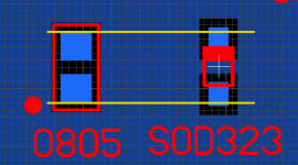
Thanks for clarifying!
I'll probably stick to 0805 then!
Regaring sourcing material - Mouser is out of Muses 72323 until May!
Digi-Key has some on the shelf!
I'll probably stick to 0805 then!
Regaring sourcing material - Mouser is out of Muses 72323 until May!
Digi-Key has some on the shelf!
Hi - Is the V1 documentation still available anywhere, can't seem to find my copy anywhere. Thanks
I plan to implement my modules with the control PCB on the front panel and two stacked volume PCBs at the rear of the chassis with ribbon cable connections.
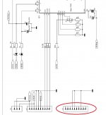
Referencing the documentation, see screengrab below, it would appear that I onlt need to use a ribbon cable between the X1 headers. The X2 header on the schematic appears to only have ground conenctions, which are also made via X1.
Am I reading this correctly?
Referencing the documentation, see screengrab below, it would appear that I onlt need to use a ribbon cable between the X1 headers. The X2 header on the schematic appears to only have ground conenctions, which are also made via X1.
Am I reading this correctly?
Attachments
Thanks for the confirmation.
I did think about just having the encoder on the front panel as per your alternative suggestion but decided that it was simplest to locate the control PCB as I plan to hook up a numeric display module.
I did think about just having the encoder on the front panel as per your alternative suggestion but decided that it was simplest to locate the control PCB as I plan to hook up a numeric display module.
Hi meldano or anyone else, I have the Musical Fidelity kWp Trivista pre amp and was wondering if you can or has anyone incorporated the Muses with an existing display? Thx.
Which remote control are you guys using with this volume control?
Currently i am using the remote for my TV, but it would be great to find a "nice" remote to use with my system 🙂
Currently i am using the remote for my TV, but it would be great to find a "nice" remote to use with my system 🙂
Sure 🙂
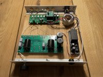
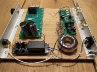
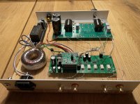
At the moment it is very much a prototype build - i am using the Muses volume and input select in front of a B1 Buffer.
The B1 power supply is a 24 V MeanWell IRM on a PCB with Mark Johnsons line filter. The "LED spider" 😉 on the main board is there because i wanted the LEDs in the prototype but with long leads so i can cut them, and use them, when i am ready with a chassis for it.
I am currently designing a linear PSU (TPS7A47) for the B1, when that is ready, all of it will be put in a box 🙂
Attachments
Thanks 🙂
For the balanced implementations: I updated the documenattion to show the balanced stacked monster principle...
For the balanced implementations: I updated the documenattion to show the balanced stacked monster principle...
It works🙂
Just need to implement that IR-receiver so I can change the steps to 0,5dB.
I saw a suggestion for Apple TV remote but it doesn't have numbers. Do you use another remote for configuring 0-9?
Thanks for excellent boards and documentation Meldano!
In a preamp with Hypnotize DCB1:

Just need to implement that IR-receiver so I can change the steps to 0,5dB.
I saw a suggestion for Apple TV remote but it doesn't have numbers. Do you use another remote for configuring 0-9?
Thanks for excellent boards and documentation Meldano!
In a preamp with Hypnotize DCB1:
Hi all,
Building up a BOM for the v2 control and comparing to some others posted here. I noticed that on your BOM, @meldano, that some cap values you've chosen differ from the schematics a bit. A couple are a bit higher. Was there a performance issue that was better solved with larger caps, or is it safe to acquire the values on the schematics?
The ones in question are the main board:
Appreciate the guidance. Some were a challenge to find on the market (REG40), but I persevered!
~Chris
Building up a BOM for the v2 control and comparing to some others posted here. I noticed that on your BOM, @meldano, that some cap values you've chosen differ from the schematics a bit. A couple are a bit higher. Was there a performance issue that was better solved with larger caps, or is it safe to acquire the values on the schematics?
The ones in question are the main board:
Code:
C10, C20: 470uF/35V ==> 1000uF/35V
C13, C23: 100uF/35V ==> 220uF/35V
     C32: 100uF/16V ==> 220uF/10V
Appreciate the guidance. Some were a challenge to find on the market (REG40), but I persevered!
~Chris
Last edited:
Second question related to the v2 volume control. I'm building a Pass Aleph P preamp that prefers the attenuation stage be after the amplification/buffer stage. Any problems with the source switching being ahead of the amp/buffer and the volume control being afterward? I haven't done a deep analysis on the schematics yet to see where the modules connect/disconnect.
It probably would have been better to figure that out before I decided on the volume control, wouldn't it have? 😛
It probably would have been better to figure that out before I decided on the volume control, wouldn't it have? 😛
Hi,
the cap values are only examples.
Choose a value between the posted values and everything will be fine.
Aleph P: it is not planned to cut the connections between the input selector and volume control. You can cut the tracks on the pcb.
You have also check the voltage output of the p and the maximum allowed signal voltage from the muses.
I think it is not a problem to put the muses at the input from the aleph p.
Daniel
Thank you, sir. Diving into the schematics a bit more. Appreciate the volume control project!
~Chris
~Chris
Hi,
the cap values are only examples.
Choose a value between the posted values and everything will be fine.
Aleph P: it is not planned to cut the connections between the input selector and volume control. You can cut the tracks on the pcb.
You have also check the voltage output of the p and the maximum allowed signal voltage from the muses.
I think it is not a problem to put the muses at the input from the aleph p.
Daniel
To be honest, I doubt that any signal I would send into this thing would ever reach that high! Well, let’s build it, scope it, and see what happens. 🙂
Edit: Just checked the Aleph J service manual and max output is reached at 1.5Vrms in. This won’t be a problem. 🙂
Edit: Just checked the Aleph J service manual and max output is reached at 1.5Vrms in. This won’t be a problem. 🙂
Can anyone comment on the maximum input value stated on the spec sheet on page 4 of the attached? I *think* I'm reading it as a maximum of 11Vrms on its input, but I'm open to second (and greater) opinions.
Much appreciated!
~Chris
Last edited: