Ben, the quote is quite correct. Those three aspects of the problem are all linear and as such are all correctable with linear electronics since at the wavelengths involved spatial aspects are not relevant. If the frequency were higher then even linear aspects of a multidimensional problem are not correctable with a one dimensional electronic solution.
I can understand how EQ can make the swept freq response as pretty as you want. No quibble there.Ben, the quote is quite correct. Those three aspects of the problem are all linear and as such are all correctable with linear electronics...
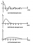
But how can EQ make transient response behave right as in the pictures below posted by GM on a recent thread showing different Q's? Resonance is a mechanical feature of the speaker.
If, heaven forbid, you had a speaker with the upper-picture bass-reflex or TH type transient response, wouldn't you need corrective feedback to tame that?
B.
Attachments
Last edited:
Ben
One doesn't need "feedback" to EQ that system to whatever "transient"(i.e. impulse) response they want - given the limitations of the sources bandwidth. If the sub has a high Q then then just correct it with a "cut" filter at resonance and the ringing will be eliminated at the same time. Impulse response (i.e. transient response) is intimately connected with the frequency response. Change one and you change the other.
One doesn't need "feedback" to EQ that system to whatever "transient"(i.e. impulse) response they want - given the limitations of the sources bandwidth. If the sub has a high Q then then just correct it with a "cut" filter at resonance and the ringing will be eliminated at the same time. Impulse response (i.e. transient response) is intimately connected with the frequency response. Change one and you change the other.
Ben
One doesn't need "feedback" to EQ that system to whatever "transient"(i.e. impulse) response they want...
I'm beginning to see the light. Although not intuitively obvious to me, I can imagine that you and the comparably well educated bolserst are correct in theory.
But in practice, you'd need inconceivable and unfeasibly potent EQ to tame the speaker resonance (and a bunch of other irregularities) to the extent that MF would achieve*, and which might still not be nice. And which at the same time would up-end the swept freq response if anybody ever wanted to try it.
My intuition is that the box has its sound and EQ'ing the input won't make that go away just as tapping on a music instrument makes it sing its note.
B.
*I avoid saying "achieve EQ to an acceptable degree" because lots of folks find it acceptable to have awful group delays
Last edited:
The difference between a Q of .7 and 1.4 is just a few dB at resonance - that's a trivial amount of EQ. Especially when compared to the room modes - those can take many dB to tame, so worrying too much about how the source works in a free field is pretty much missing the forest for the trees.
Although no DIYer should rest until they tune their speakers in-situ, not helpful to continue to muddy the discussion with room responses.The difference between a Q of .7 and 1.4 is just a few dB at resonance - that's a trivial amount of EQ. Especially when compared to the room modes
I'd like to see some empirical demonstration of what you say, esp if we could start posting tone-burst responses on this forum*, like were standard in yesteryear. While it seems clear you can make a speaker FR flat and therefore lower the nominal mathematical Q, I am still wondering if that would change the ringing seen on impulses or tone-bursts much.
B.
*Can anybody critique the value of the Hann-shaped tone-burst signal in REW?
Last edited:
Earl is right, you can EQ a driver to any target no matter what the un-eq'd Q was, it will now have the new Q and associated behaviour (also in the time domain, hence). There will be a difference for signals that are outside of control of the voice coil source signal, eg. any (gross) distortion and/or exitation from the outside will still exite "ringing" with the original Q.... which is only a problem when this Q is extremely high...
Last edited:
Have you tried? I’ve never had any difficulty with it. You continue to think of dynamic drivers as wild untamed beasts with hidden resonances just waiting jump out and wreak havoc. In reality, most woofers built in the last 20years have predictable minimum phase behavior at “sub-woofing” frequencies when driven within reasonable limits.…you…are correct in theory. But in practice, you'd need inconceivable and unfeasibly potent EQ to tame the speaker resonance (and a bunch of other irregularities)
Rather than focusing on the impedance peak you see at resonance on an impedance plot, concentrate on the fact that the acoustic response of a woofer is proportional to cone acceleration not impedance, and is a HP filter. You wouldn’t be scared of a HP electronic filter, and likely have no issue with the idea that a second filter can be put in series with it to modify the overall response. The first filter still retains its original response, but the overall input-to-output response thru the two series connected filters can easily be manipulated to your liking. In the case of a woofer, it is just a mechanical HP filter rather than an electronic filter.
Correct, the (woofer+box) retains its inherent response even when EQ is added upstream that changes the overall input-to-output response. Similarly, you can appreciate that the sound of tapping on a musical instrument would change if you EQ the frequency content of the “tap”.My intuition is that the box has its sound and EQ'ing the input won't make that go away just as tapping on a music instrument makes it sing its note.
I’d recommend you perform the tests I suggested earlier in the thread, Post#173. Basically, forget about the woofer at first and just put an EQ in your line-level measurement loop. Change the frequency response by setting different HP and/or LP frequencies, roll-off rates, and Q. Then see how the impulse response (or response to tone bursts if you prefer) is affected by the frequency response. Once you get a feel for how frequency response and transient response are tied to each other you can better understand measured woofer response. Put your Brutus 15” woofer in a 2-3 cubic foot box and give it a try. You will find that the transient response for a woofer or (woofer + EQ) will be identical to just the EQ set to the same overall input-to-output frequency response.…I'd like to see some empirical demonstration of what you say, esp if we could start posting tone-burst responses on this forum, like were standard in yesteryear. While it seems clear you can make a speaker FR flat and therefore lower the nominal mathematical Q, I am still wondering if that would change the ringing seen on impulses or tone-bursts much.
Concerning tone bursts:
I don't know of a way to easily look at tone bursts with REW. However, ARTA can be used to generate and capture tone bursts.
If you don’t want to bother with ARTA, but have an oscilloscope, I could send you *.wav files of any tone burst frequency and envelope you are interested in looking at.
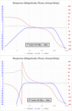
Remember, group delay is not a separate issue from frequency or transient response. Group delay is just a measure of how rapidly phase response is changing with frequency, and the phase response is directly tied to the frequency response. You can't change one without changing the other two as well. When you say people like awful group delays, you are saying they like bass response that has a sharp knee and a rapid roll-off. You can prove this to yourself by performing the EQ loop test mentioned above, measuring with REW, and plotting the frequency response and group delay. For starters, compare group delay measurements for 1st order and 4th order 30 Hz HP filters. They will look like the attached pic generated with the square wave visualizer spreadsheet.… lots of folks find it acceptable to have awful group delays
Download spreadsheet file: Post#361
Additional example plots: Post#256
Attachments
Hi,
when experimenting with dipole and CB woofers it seemed to me that drivers with Qts of >0.8 always sounded less precise than lower Qt drivers even when I carefully equalized both to almost the same amplitude response.
And I´m quite conviced, that the mechanical filter system ´dynamic driver´ doesn´t behave equal to a electrical filter with same (synthezised) parameters.
When talking about the driver as filter it should be kept in mind, that the parameters derived by measurement, Thiele/Small and others are just values applying to a single specific amount of drive power.
They change considerably over the full power range, while an electrical filter remains rather unaffected.
As such we equalize a dynamically variable mechanical filter with a static electrical filter.
Before finally settling with CB woofers where the differences seem rather small I also experimented with equalized BR-woofers of 5th and 6th order (relying on high Q-values of the resonator).
I never could achieve a highly precise bass with those, compared to CB woofers equalized to similar amplitude response.
They always exhibited a recognizable degree of boominess.
With the high-order BRs a high-Q mechanism is hidden below the lower Q of the overall measured amplitude response.
Just another hint for me that mechanical filters and electrical filters don´t behave (and sound) the same and that a simple view on amplitude and phase response only (deducting all other parameters from those two) simply falls too short.
It could also well be that praxis and theory match better under free-field or reflection-free conditions for those BRs, but under normal listening room conditions the equalized high-order BRs sucked sonically.
I understand and share the doubts that Ben has mentioned .... which is for just the second time in all those years we contribute that we agree on something .... now, if that isn´t a proof! 😉
jauu
Calvin
Last edited:
bentoronto's 15" Brutus Speaker
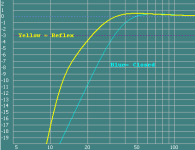
I don't know if the driver is this one, Brutus BRZ15D4, or the size of the box ? I got the T/S PDF direct from their www. Anyway, here's some of those Evil sims of it 😀
Sealed 200L Box & no HPF - f3 = 31Hz, Qtc = 0.7, GD @ 16Hz = 9.5ms, Max Power @ 16Hz = 172W, Max SPL @ 16Hz = 98 dB - Below 16Hz Xmax is exceeded
Reflex 200L Box & no HPF - f3 = 21.5Hz, GD = 30ms, Max Power @ 16Hz = 300W, Max SPL @ 16Hz = 109 dB - Below 16Hz Xmax is exceeded
Reflex 200L Box & 24dB LR HPF @ 12.5Hz - fb = 16Hz, f3 = 23Hz, GD = 56ms, Max Power @ 16Hz = 300W, Max SPL @ 16Hz = 109 dB - Below 16Hz Xmax is NOT exceeded
Attachments
After the big snowstorm in Fort McMurray, Alberta (57N lat.) last night at my departure, glad to be back to these peaceful discussions.And I´m quite convinced, that the mechanical filter system ´dynamic driver´ doesn´t behave equal to a electrical filter with same (synthezised) parameters.
...
Just another hint for me that mechanical filters and electrical filters don´t behave (and sound) the same and that a simple view on amplitude and phase response only (deducting all other parameters from those two) simply falls too short.
Not unlike Calvin and me, I sense the EQ-can-fix-all posters also seem to have "but..." qualifications in their posts. "But..." inserting EQ to counteract each and every bump in a freq response (which nobody doubts can make the freq response as flat as you please) in conformity with the steady-state T/S model, may not make the dynamic behaviour of a speaker perfect because the T/S model may just not fit well.
I think we are like the crisis amp development of the 1940s. FR and THD did not seem to tell the whole story at that point in time. Likewise, the FR seen on this forum doesn't tell the whole story.
bolserst is right that we need better testing; that would address Calvin's observations and the "but..." others have. The FRs we see posted in this forum may (at the best of times) match the predictions of T/S. But certainly not a very rounded picture of speaker performance. How come nobody posts tone bursts or impulses?
It would be nice to see another thread devoted to what the testing should be going forward. In the meantime, I'm trying to figure out how to photograph impulses on my oscilloscope screen. Any suggestions? But first I have to figure out what is the most informative stimulus to throw at a sub?
B.
Indeed! 😀… I understand and share the doubts that Ben has mentioned .... which is for just the second time in all those years we contribute that we agree on something .... now, if that isn´t a proof!
Do you happen to remember the drivers you were comparing? Is it possible the driver with Qts>0.8 did not have as good a suspension and magnetic design as the lower Qts drive you were using? One way I experimented with comparing mechanical vs electrical adjustment of Qtc was to use a DVC driver in an optimized CB. I compared driving both VCs vs. driving just one VC with electrical EQ applied to match response. This allowed comparison of Qts difference of nearly factor of 2 while avoiding the possibility of differing suspension or magnetic non-linearities from clouding the results....when experimenting with dipole and CB woofers it seemed to me that drivers with Qts of >0.8 always sounded less precise than lower Qt drivers even when I carefully equalized both to almost the same amplitude response.
Absolutely. I whole-heartedly agree. This is one of the main reasons for my interest in MFB.When talking about the driver as filter it should be kept in mind, that the parameters derived by measurement, Thiele/Small and others are just values applying to a single specific amount of drive power. They change considerably over the full power range, while an electrical filter remains rather unaffected.
If you are mathematically inclined, you can actually take the Klippel test results for BL, Cms, and Le vs. stroke and perform a dynamic simulation of the cone motion with different forcing function frequencies. The results match measured waveform distortion shape rather well.
However, this tangent discussion was started by bentoronto’s comment that he didn’t care about such non-linearities. He was mainly interested in using MFB to flatten response and shape roll-off for low group delay, which EQ can do just as well, but without the benefit of reducing the non-linear distortion. I probably should have lead with that caveat.
If yours is a dual trace oscilloscope all you need to do is feed it repetitive impulses; one input getting the impulse from the amplifier, and the other from the microphone. Trigger off the one from the amplifier and set your repetition rate til you get a stable waveform that fits nicely on the screen. Alternatively, for < $100 you can get a PC based oscilloscope program (or ARTA) which has the ability to perform single capture and hold after a trigger.I'm trying to figure out how to photograph impulses on my oscilloscope screen. Any suggestions? But first I have to figure out what is the most informative stimulus to throw at a sub?
I think the most informative measurement is still frequency/phase response, followed by distortion vs output trends. Whatever you see in an impulse or tone burst waveform will likely be more easily understand by the previously mentioned measurements. I say this because the look of tone bursts change considerably with frequency/phase response changes even in the ideal case of zero distortion. For example, looking at a 60 Hz tone burst and you change the LP crossover frequency control a bit…the leading and trailing edges of the burst change. Without knowing what the frequency/phase response was you would have no idea if the change in the tone burst you saw was due to non-ideal mechanical behavior of the driver or not.
But, like you, I would definitely be interested if somebody has found another measurement or stimulus that captures subwoofer performance better.
Hi bolserst,
In a response to Bentoronto you state (#657) that transient behaviour, Q and Group Delay are only function of linear distortion and later on in a response to Calvin (#672) you agree that Thiele/Small change considerably during cone travel. In other words, now you make them part of nonlinear distortion as well... ;-)
P.s. dont forget waterfall measurements.
Regards,
Djim
Hi,
I already had some more text in mind for my latest post, dealing with exactly the issue that two different setups means rather too many variables changing at the same ... but then I decided the post would become too long 😉
DVC drivers and extra magnets appear a practical way to change driver parameters without changing mechanical parameters.
jauu
Calvin
I just remember it were two different ones.Do you happen to remember the drivers you were comparing?
I already had some more text in mind for my latest post, dealing with exactly the issue that two different setups means rather too many variables changing at the same ... but then I decided the post would become too long 😉
DVC drivers and extra magnets appear a practical way to change driver parameters without changing mechanical parameters.
jauu
Calvin
Would the Holland & Newell Modulation Transfer Function ( MTF) have any added value to the current discussion between Ben+Calvon vs Bolster+Earl?
See here http://eprints.hud.ac.uk/3584/1/IOA_Proceedings_Vol27-8_RS21-2005.pdf
I would be very interested to learn whether measurement of the MTF is worthwhile & has any added value, or just as useless for loudspeaker design as the CEPSTRAL analysis of loudspeakers these gentlemen presented some 20 years ago.
Eelco
Hi,
I see almost only agreement. 😉
The remaining Q as I see it is:
are the differences between a equalized and MFB system that are due to power related behaviour of the mechanics prominent enough to make an clear audible difference?
For my part I´ve given up most of my activities around MFB and rather invest in better low-THD (though often costier) drivers in CBs and simple equing.
Haven´t read the linked article yet, but the title imples that it deals with (power-)variable eqs to match the variable mechanical filter, which would close the ´behavioural gap´ between eq und MFB even more.
jauu
Calvin
Good pc based test:
Obtain small signal impulse response via log sweep + convolution.
Check for low distortion and good S/N ratio.
Choose test signal, bursts, music, whatever... and convolve with IR.
Record test signal directly, mic must be in the same exact position.
Level and time align, then subtract, adjust for deepest null.
The residual is all the noise and distortion your driver is making, and it will skyrocket, drift and wander, especially when you crank it, and dynamic alignment shifts really become apparent
MFB or ultra conservative design comes out best. Undersized ported comes out worst.
...
MFB or ultra conservative design comes out best. Undersized ported comes out worst.
Klaus,
well designed ported enclosures reduce cone excursion at the lower end by a factor of e.g. 4 easily.
Neither is it plain nor useful comparing "misaligned" or even "misdimensioned" systems with well aligned ones, regardless of technology used: So imo we should do away as soon as possible in spreading "legends" and/or "folklore" in electroacoustics.
With ported designs reductions in THD and noise, which are grossly proportional to the reduction in cone excursion - depending on actual motor topology and suspension of the driver - are achievable.
Using comparable drivers in terms of distorsion/destruction limits based on displaced volume, you cannot even compare a CB at LF to the BR enclosure at highest possible levels (BR), because destruction limits of the driver in a CB will be exceeded by far.
Even stating MFB could impose comparable effects (?) in
- reduction of THD and noise
- extension of maximum SPL within given limits of distorsion (or even destruction)
is simply insupportable.
Of course it is important not to operate the BR System not too far below fb.
Last edited:
I know all this but its not relevant to the question, which was propose a test signal / strategy for fidelity.
Btw, biggest offender in ported systems is port noise and few system really can cope with a sine at port resonance at high level, so the excursion reduction buys you nothing when chuffing dominates.
And yes, sine bass at high levels is normal music signal these days.
Btw, biggest offender in ported systems is port noise and few system really can cope with a sine at port resonance at high level, so the excursion reduction buys you nothing when chuffing dominates.
And yes, sine bass at high levels is normal music signal these days.
- Home
- Loudspeakers
- Subwoofers
- Commercial motional feedback woofer available sort of