Some relaxing pictures
I know that you are enjoying seeing pieces of craftsmanship, like myself.
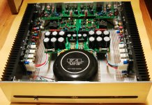
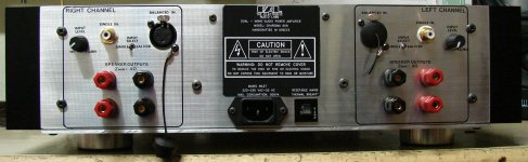
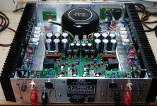
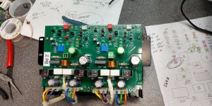
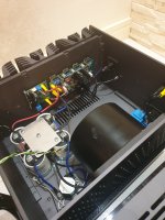
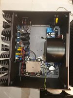
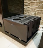
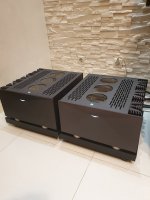
Here some pics of the partner, a homemade 2X170W/8Ω Class AB BJT amplifier built 12 years ago.
I know that you are enjoying seeing pieces of craftsmanship, like myself.
Here some pics of the partner, a homemade 2X170W/8Ω Class AB BJT amplifier built 12 years ago.
Attachments
Last edited:
Thanks for your love")
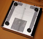
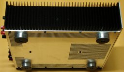
A detail that is not easily visible, is that the two top-bottom covers are made from 3mm thick alu sheet and are screwed tightly on the 2 heatsinks, thus working as assistants in heat moving. Actually, the whole casing (included the 4mm front panel) is running almost the same hot in any instance
A detail that is not easily visible, is that the two top-bottom covers are made from 3mm thick alu sheet and are screwed tightly on the 2 heatsinks, thus working as assistants in heat moving. Actually, the whole casing (included the 4mm front panel
) is running almost the same hot in any instance
Last edited:
Pioneer SX-750 into the 21st Century one PCB at a time
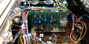
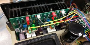
Finished my personal project - bringing my Pioneer SX-750 into the 21st century - one PCB at a time!
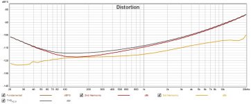
Finished today - Version 3.1 of the amplifier replacement board. THD-1 at full power: 0.0009% with Transitional Miller Compensation (TMC)
Previous PCB replacement - the Regulated Power Supply/Protection circuit board. More efficient (much less waste heat), adjustable with better regulation, and looking much more high-tech being almost all SMD devices.
Finished my personal project - bringing my Pioneer SX-750 into the 21st century - one PCB at a time!
Finished today - Version 3.1 of the amplifier replacement board. THD-1 at full power: 0.0009% with Transitional Miller Compensation (TMC)
Previous PCB replacement - the Regulated Power Supply/Protection circuit board. More efficient (much less waste heat), adjustable with better regulation, and looking much more high-tech being almost all SMD devices.
Attachments
I know that you are enjoying seeing pieces of craftsmanship, like myself.
Here some pics of the partner, a homemade 2X170W/8Ω Class AB BJT amplifier built 12 years ago.
Pro looking.
I know that you are enjoying seeing pieces of craftsmanship, like myself.
Here some pics of the partner, a homemade 2X170W/8Ω Class AB BJT amplifier built 12 years ago.
good morning, fotios.
very good job, really professional. congratulations!
I know that you are enjoying seeing pieces of craftsmanship, like myself.
Here some pics of the partner, a homemade 2X170W/8Ω Class AB BJT amplifier built 12 years ago.
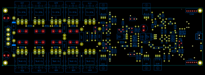
PCB Layout please 😊
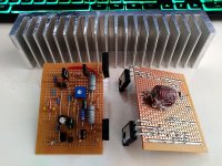
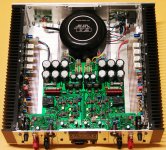
I am very happy that I finally managed to finish this project with TSSA V4 amplifier. I made a dual mono variant, with 2x52VAC / 1000VA transformer, with RIFA PEH169 capacitors. Very detailed, huge dynamics, fast bass and fist, I just love it.
Attachments
case
Are you sure ? Did you ask how much total bias it has?
Are you sure ? Did you ask how much total bias it has?
1/3 of the heatsinks are for decorative reasons!
Are you sure ? Did you ask how much total bias it has?
As i can see the output devices are bolt to the 2/3 of the heatsinks as active cooling!
So no matter how much total bias it has( the more bias the worst thermal resistant to the third party of the sink even thermal paste applied) temperature measurements will tell you the truth
Well build box for the show not for the go!
You need to redesign your board if you want to get the most from your <high bias> amp with your chosen box
Last edited:
- Home
- Amplifiers
- Solid State
- Post your Solid State pics here