Проект Union
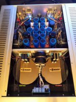
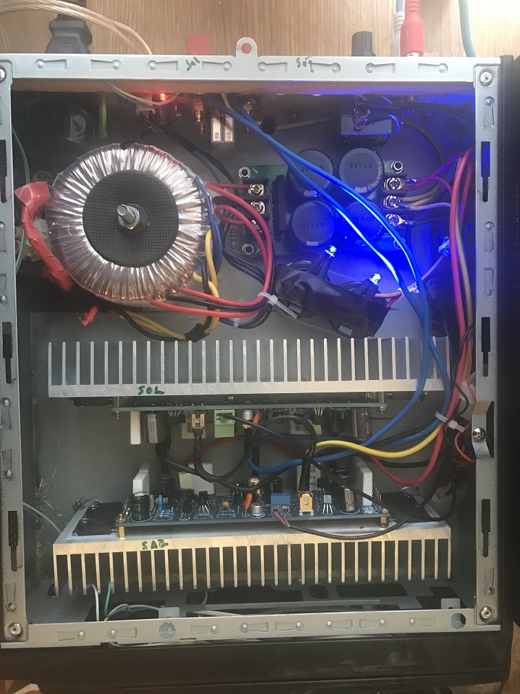
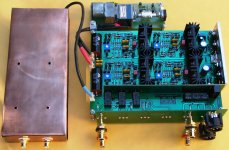
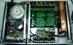
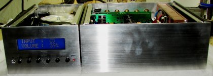
hi! this amplifier, as a result of my many years of research, was developed for my friend. The amplifier is a complete dual mono. Amplifier Features: No overall negative feedback, Class AB-rated power 160 W at 4 ohms, non-linear distortion-0.009% first watt, 0.06 at rated power. Built-in relay volume control, soft start system. Four toroidal transformers: 2 x 400W to power the voltage amplifier and output stages, one to power the protection and one to power the volume control. All electronic components were repeatedly listened to and selected as efficiently as possible. In the power supply unit with a capacity of 410000 uf, Mundorf capacitors of the HC 47000 and AG 15000 uf series were used in combination with BC components 056 series. This combination had a positive effect on the sound.
hi! this amplifier, as a result of my many years of research, was developed for my friend. The amplifier is a complete dual mono. Amplifier Features: No overall negative feedback, Class AB-rated power 160 W at 4 ohms, non-linear distortion-0.009% first watt, 0.06 at rated power. Built-in relay volume control, soft start system. Four toroidal transformers: 2 x 400W to power the voltage amplifier and output stages, one to power the protection and one to power the volume control. All electronic components were repeatedly listened to and selected as efficiently as possible. In the power supply unit with a capacity of 410000 uf, Mundorf capacitors of the HC 47000 and AG 15000 uf series were used in combination with BC components 056 series. This combination had a positive effect on the sound.
Attachments


Last edited:
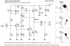
My first " JLH 1969 AMP 10W".

Attachments

Fine looking build zdr!
p.s. That's a nice track from Sara K. (Hell or High Water) you have playing in your PGA preamp video on Youtube. 🙂
p.s. That's a nice track from Sara K. (Hell or High Water) you have playing in your PGA preamp video on Youtube. 🙂
Last edited:
simple kits
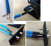
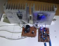
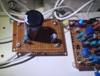
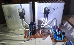
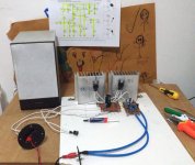
My simple design as, micro PC box, speaker protection, 2x L12-2, 3300uf x 4 cap + 2x10000uf cap (installation of 2 cap not good but, it couse no problem), neglect the blue leds (bleeder leds 🙂 ), 100k pot., 1.5mm diameter cables, 2x20v ac toroidal. thats so.
My simple design as, micro PC box, speaker protection, 2x L12-2, 3300uf x 4 cap + 2x10000uf cap (installation of 2 cap not good but, it couse no problem), neglect the blue leds (bleeder leds 🙂 ), 100k pot., 1.5mm diameter cables, 2x20v ac toroidal. thats so.
Attachments

Last edited by a moderator:
Nice screen zdr!!!
Is the project publised someware here?
What is the MCU?
Nice screen zdr!!!
Is the project publised someware here?
What is the MCU?
Thanks. Both pga pre and power amp are published here:
Compact TPA3255 design with PFFB and single PS
Compact TPA3255 design with PFFB and single PS
Arduino+PGA2311 Ultimate PreAmp with OLED and IO switching
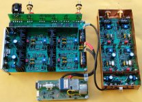
An all-discrete preamp
A brief description:
Is a complete preamp, including RIAA equalizer into the separate copper casing.
All stages are implemented with BJTs.
The DC offset of each stage is precisely trimmed, providing the possibility of DC-coupling among stages, and eliminating the need for big AC-coupling capacitors, ensuring thus a flat HF response at any signal level.
The RIAA stage is configured for a gain of 2,000 to be compatible with all MM and high-output MC cartridges.
On the main board, the first stage works as buffer and can be configured either as voltage follower (gain=1) or as non-inverting (gain=2 or more). In the voltage follower configuration, the frequency response is close to 1MHz.
The second stage works as inverter with gain=1 to provide balanced output.
The whole thing is supplied with +/-24Vdc, ensuring thus a tremendous headroom.
It can directly drive headphones.
All PCBs are home made.
Attachments

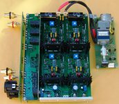
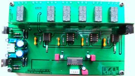
An all-discrete preamp, control board
Ευχαριστω πολυ Θυμιο, εισαι ευγενεστατος
(Thanks Thimios, you are very kind)
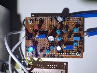
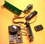
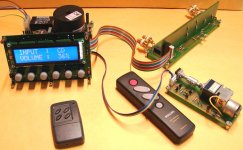
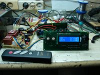
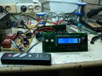
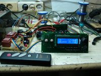
Here is the control circuit.
It has its own power supply.
As I've built this project 10 years ago, an old fashioned PIC16F887 is used as host MCU!
The 6 functions are controlled either manually by 6 rugged tactile switches, or remotely.
Some details regarding the volume pot: Since it is controlled by push switches, there is no need for an external knob. The small pot coupled to the axis of mot-pot is connected to the ADC input of micro and its output voltage is precisely translated to percent from 0-99% (I've selected that instead of dB, because of the 2 possible configurations of the buffer either max=0dB or max=+3dB) that corresponds to the volume setting by the mot-pot.
Ευχαριστω πολυ Θυμιο, εισαι ευγενεστατος
(Thanks Thimios, you are very kind)
Here is the control circuit.
It has its own power supply.
As I've built this project 10 years ago, an old fashioned PIC16F887 is used as host MCU!
The 6 functions are controlled either manually by 6 rugged tactile switches, or remotely.
Some details regarding the volume pot: Since it is controlled by push switches, there is no need for an external knob. The small pot coupled to the axis of mot-pot is connected to the ADC input of micro and its output voltage is precisely translated to percent from 0-99% (I've selected that instead of dB, because of the 2 possible configurations of the buffer either max=0dB or max=+3dB) that corresponds to the volume setting by the mot-pot.
Attachments
@mdardeniz
It's just like pro work; congratulations. Why the work is not in a box? Don't you use it?
Thanks a lot for your kind words.@Trelolelo
Fotios, just a perfect job...very nice....thumbs UP!
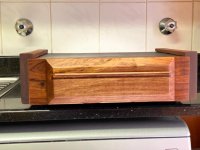
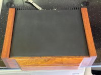
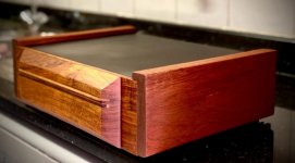
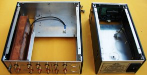
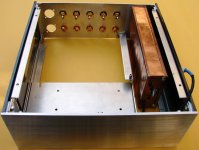
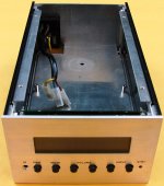
Yes, it is in use. Here some pictures of the homemade casing.
Attachments
Excellent work!
It remembers me a PGA2310 preamp that I had built 10 years ago.
Here some pics.
Attachments
- Home
- Amplifiers
- Solid State
- Post your Solid State pics here