Bob Cordell said:Its very good to think with a clear head in the absence of what has gone before, and not be self-inhibited by that sort of thing.
Hi Bob!
So this is Bob Cordell. Heard a lot about you, now I know what you sound like! 🙂
At least having done what you agreed with above, I did not post with any pre-conceived idea about you! (Feeling somewhat guilty, I will still read the whole thread, but more at my leisure than 3:00 in the AM.) Also trying to keep post brief and thus sometimes not being too explicit , my position is that at least let conventional thinking not blinker one to overlook interesting looking byways. I like hiking and often went such-a-way, only to discover what others did, that it leads nowhere. But at least then I had a bit of view the conventionalists missed. In science (I was paid to do research) this can be more important: Not to reject conventional thinking until proven wrong but also not to be limited by it - I guess that is what you are saying. Recalling GB Shaw (Man and Superman):
"The reasonable man adapts himself to the world; the unreasonable one persists in trying to adapt the world to himself. Therefore all progress depends on the unreasonable man."
Perhaps a bit simplistic, but food for thought. No, I am aware of Otala's weaker moments, but also do not appraise people by the worst or the last game they played (not implying that you do). Others granted me that privilege. Thus the particular mentioned piece by Otala had value for me, shall we say, despite ......
See what you have done now, off thread I went! At least it was feedback, if hopefully not negative! Thanks for your reply.
Regards.
Johan Potgieter said:
Hi Bob!
So this is Bob Cordell. Heard a lot about you, now I know what you sound like! 🙂
At least having done what you agreed with above, I did not post with any pre-conceived idea about you! (Feeling somewhat guilty, I will still read the whole thread, but more at my leisure than 3:00 in the AM.) Also trying to keep post brief and thus sometimes not being too explicit , my position is that at least let conventional thinking not blinker one to overlook interesting looking byways. I like hiking and often went such-a-way, only to discover what others did, that it leads nowhere. But at least then I had a bit of view the conventionalists missed. In science (I was paid to do research) this can be more important: Not to reject conventional thinking until proven wrong but also not to be limited by it - I guess that is what you are saying. Recalling GB Shaw (Man and Superman):
"The reasonable man adapts himself to the world; the unreasonable one persists in trying to adapt the world to himself. Therefore all progress depends on the unreasonable man."
Perhaps a bit simplistic, but food for thought. No, I am aware of Otala's weaker moments, but also do not appraise people by the worst or the last game they played (not implying that you do). Others granted me that privilege. Thus the particular mentioned piece by Otala had value for me, shall we say, despite ......
See what you have done now, off thread I went! At least it was feedback, if hopefully not negative! Thanks for your reply.
Regards.
I like your hiking analogy. Even if free-thinking only yields something of value 10% of the time, that is a big payoff. Good, creative engineers are never afraid to consider or even voice a hair-brained idea, but they also know how to subsequently evaluate its merit objectively.
Cheers,
Bob
Hi Graham
Seriously about your simulation:
The results are all but unexpected, every amplifier with finite damping includes some infuence of load impedance in its frequency response.
Frequency amplitude response, phase response and group delay are highly correlated and interdependent with each other and you can calculate the two of them from anyone in most circuits (phase-minimum criterion).
What am I missing?
The peaked response you've noticed in post788 means that the compensation schem gives a peak in feedback factor occurung at some frequency. This is exactly what it is intended to do!!!
At low enough frequency the miller loop including output is basically idle, because it is below compensation freuency, then it works as nested feedback, going back to typical miller compensation at 100s of kHz.
This must result in peak in closed loop freuency response but only small fraction of dB. Again you may see this effect both at amplitude, phase and group delay respone,which are perfectly interdependent.
regards
Adam
darkfenriz said:Hi Graham
Seriously about your simulation:
The results are all but unexpected, every amplifier with finite damping includes some infuence of load impedance in its frequency response.
Frequency amplitude response, phase response and group delay are highly correlated and interdependent with each other and you can calculate the two of them from anyone in most circuits (phase-minimum criterion).
What am I missing?
The peaked response you've noticed in post788 means that the compensation schem gives a peak in feedback factor occurung at some frequency. This is exactly what it is intended to do!!!
At low enough frequency the miller loop including output is basically idle, because it is below compensation freuency, then it works as nested feedback, going back to typical miller compensation at 100s of kHz.
This must result in peak in closed loop freuency response but only small fraction of dB. Again you may see this effect both at amplitude, phase and group delay respone,which are perfectly interdependent.
regards
Adam
Hi Adam,
These points you have made are right on target.
Bob
Hi Adam,
Thank you for keeping thoughts on topic, and for asking a straightforward question about post#788 that is indeed right on target!
So those group delay variations were expected, or, is it that when they are pointed out they become obvious? I am not trying to be smug, but oh - how I have been chided in the past for daring to suggest that C+L+R filters as used within amplifier circuits, or an amplifier itself, behaves anything other than as if with a constant group or propagation delay, and that they cannot thereby generate a non-linear response in time !!!
It is only when you study NFB controlled responses under reverse excitation or with realistic loads that you can begin to observe deviations which do not arise when amplifiers are seen as simplistic 'group/propagation delaying' gain blocks.
Also, the 'finite' damping of a NFB amplifier depends upon the circuitry and current activity arising within the global loop, so 'finite' cannot be assumed to be constant with frequency in time, because it becomes modified by loading and inner loop induced reactions.
You wrote >>Frequency amplitude response, phase response and group delay are highly correlated and interdependent with each other and you can calculate the two of them from anyone in most circuits (phase-minimum criterion).
What am I missing?<<
I don't know. That sounds most reasonable to me.
However, loudspeaker current wrt voltage waveform renders the 'frequency amplitude response, phase response and group delay' of so many amplifiers variable wrt to source, such that currents flowing within internal circuitry no longer bear direct relationship with either input or output potentials.
Where currents are not coherent with voltage, the group/control delay alternates in time at different frequencies. Currents can end up in quadrature (sometimes worse) and any related voltage drops become superimposed non-linearities that global NFB cannot attempt to eradicate faster than the enclosed 'open loop' can respond.
ie. the NFB control is not coherent wrt source waveform, and the resultant is audible.
Yes, the compensation scheme being discussed peaks at some frequency. This indicates a degree of tuning and phase change within the inner loop, which cannot fail but to result in voltage superimpositions when some frequency bands of load currents are no longer in phase with input voltage, especially at moments of output conduction crossover with phase shifted load current.
I think we would agree that the fractional dB peak at some frequency is merely a global loop minimised indicator of this internal phase change.
When the current flow necessary to drive the VAS base *plus its directly connected 'nested' feedback arrangement* is not coherent with input (not a flat open loop gain/phase at AF) the differential stage (especially if fitted with emitter resistors) (also if the input base driving impedance is high) cannot transconduct as 'intended' and as is necessary to coherently control lagging/leading alternations of output terminal voltage at all AF frequencies.
Do you percieve that I am missing something?
Cheers ...... Graham.
Graham Maynard said:
So those group delay variations were expected, or, is it that when they are pointed out they become obvious?
I guess you know the answer 😉
The results would have been expected if I had analysed them thoroughfully.
You are giving the facts, which are undisputable and then conclude things that are not obvious at all.
However are you suggesting RCL networks give non-linear response?
RLC circuits are linear and time invariant, by (love-making) definition as long as other parasitic phenomena don't occur, like inductor BH saturation.
Also I do not understand what you mean under 'propagation delay' term. Connected to speed of light? Or group delay?
Where currents are not coherent with voltage, the group/control delay alternates in time at different frequencies. Currents can end up in quadrature (sometimes worse) and any related voltage drops become superimposed non-linearities that global NFB cannot attempt to eradicate faster than the enclosed 'open loop' can respond.
You jump too huge leap from facts to conclusions without enough reasoning, so that I do not know what to say.
Group delay alternating in time at different frequencies definitely occurs and it is related with non-constant pole frequency with signal or a mixture of non-linearity and dynamics, but it seems to fall into PIM or AM/PM distortion criterium. Though I cannot imagine poles being modulated so hard to make currents add in quadrature...
Current driving VAS base is not coherent with input much. Rather with error between input and output.When the current flow necessary to drive the VAS base *plus its directly connected 'nested' feedback arrangement* is not coherent with input (not a flat open loop gain/phase at AF) the differential stage (especially if fitted with emitter resistors) (also if the input base driving impedance is high) cannot transconduct as 'intended' and as is necessary to coherently control lagging/leading alternations of output terminal voltage at all AF frequencies.
The use of the word 'cannot' again leaves some gap of resoning to me, explain please.
I think it can, this is actually how feedback works, drives differential stage so that it can drive VAS so that VAS can drive output stage so that voltage at speaker terminals is close to multile of input no matter what the load is.
Feedback works this way until total phase shift is relatively low, compensates poles with zeros, zeros with poles and non-linearities with anti-non-linearities, if not, the oscillation happens or some sort of dynamic instability.
Honestly I don't understand why you are so confused about calss B and reactive loads and so on.
regards
Adam
Hi Adam,
Your last 'personal' sentence is condescending, assumptrive, and hardly makes me feel like attempting to overcome the communication hurdle that exists.
You have no right to say that I am confused just because I have difficulty in communicating with you who applies appreciation methodologies and uses terminologies I deliberately choose to NOT use because I feel they obstruct clear thinking.
Sure even with calculus sometimes one has to take leaps which are not obvious and cannot be proven correct until verifiable results are obtained.
I thought we might be getting somewhere here, but I've had enough. There is such a lack of patience and manners it is simply not worth my genuine efforts.
Those who believe they understand SS NFB amplifiers need to ask themselves why it is that even though all the 'nodes and zeros etc. etc.' are theoretically correct, so often the reproduction still does not sound right !!!!!
Sorry if you felt offenced, I never meant it, I rather meant that you don't accept the well-established theories, measurements and reasoning concerning class B and dynamic loads.
Notice, that I am at First-Certificate level of English and please try to be more forgiving.
I would be glad if we left personal part and go back to technical.
Though I believe you are a nice person and so am I 😀
but that's not really a place for anything but technology...
Sorry again and please continue
regards
Adam
Hi Graham,' confused and concerned'? I am about some criticisms here. ;-)
Your work looks interesting. I hope to read it more carfully in future.
Your work looks interesting. I hope to read it more carfully in future.
Hi Graham,
I'm sorry to jump in this thread, without having some information to share regarding feedback. But I can share this personal experience:
Wrong terminology because I'm lazy, in a hurry or don't it better, this could happen to me all the time.
But different language to sharpen things out...no, not any more!
Regards
Jürgen
I'm sorry to jump in this thread, without having some information to share regarding feedback. But I can share this personal experience:
I have bad experience with this myself and I won't try it again.Graham Maynard said:
You have no right to say that I am confused just because I have difficulty in communicating with you who applies appreciation methodologies and uses terminologies I deliberately choose to NOT use because I feel they obstruct clear thinking.
Wrong terminology because I'm lazy, in a hurry or don't it better, this could happen to me all the time.
But different language to sharpen things out...no, not any more!
Regards
Jürgen
juergenk said:I'm sorry to jump in this thread, without having some information to share regarding feedback.
But you ARE providing information regarding feedback, J, - communication feedback ....
As I promised earlier I am making a valiant effort to read through this large thread - and I am becoming aware that communication "feedback" is perhaps a greater problem than electronic feedback. For in the former the only "measuring instrument" that one can hook up, is the intellects of BOTH communicators. (That is even before language comes into the equation.)
Where I worked in research, this was an almost daily obstacle. Fortunately there disagreeing parties could both go to the experiment and sort matters out. (And one couldn't go the the BOSS! He would take 500 mS of reaction time and shoot right back at you: "Oh? Well sort it out! I thought that's what you are being paid for!!" Good old times.)
I was fortunate. I was not good at it (having grown up an only child), but I worked in an atmosphere where I became good at it (well, such as "good" might be).
Regards to all parties.
Deriving SPICE Models for Speakers
I'm not sure if this is the best thread to post this message, but I did see some posts regarding the non-ideal load that speakers present to an amp.
Is there a convenient way of extracting a lumped element model for a given loudspeaker? It is one thing to simulate an amp design into a resistive load, or even an R || C load, but an actual model of the speaker would be much better.
I could open up the cabinet, figure out the crossover component values, but that still leaves the speakers themselves. The model should also include the effects of backdriving caused by the mechanical inertial of the speaker.
Thanks in advance.
Hi Analog_Guy,
--- non-ideal load that speakers present to an amp.---
What hell could be ideal loads ? Purely resistive ones ?
It is sometimes been forgotten that the prime objective of negative feedback is not to reduce distorsion but to maintain constant the voltage gain whatever the load.
--- non-ideal load that speakers present to an amp.---
What hell could be ideal loads ? Purely resistive ones ?
It is sometimes been forgotten that the prime objective of negative feedback is not to reduce distorsion but to maintain constant the voltage gain whatever the load.
Re: Deriving SPICE Models for Speakers
May be some work of mine 2 years back can help in this direction.
http://www.diyaudio.com/forums/showthread.php?postid=674544#post674544
In the speakers forum you will find much more help and qualified advisers.
Rodolfo
analog_guy said:.....
Is there a convenient way of extracting a lumped element model for a given loudspeaker? It is one thing to simulate an amp design into a resistive load, or even an R || C load, but an actual model of the speaker would be much better.
.....
May be some work of mine 2 years back can help in this direction.
http://www.diyaudio.com/forums/showthread.php?postid=674544#post674544
In the speakers forum you will find much more help and qualified advisers.
Rodolfo
forr said:It is sometimes been forgotten that the prime objective of negative feedback is not to reduce distorsion but to maintain constant the voltage gain whatever the load.
That happens, Forr, but as prime objective? I would shift the emphasis. Constant voltage gain, at least into practical loads, was there before NFB. Inaudible distortion can only be achieved with NFB which to me makes that the prime objective. When I decide how much NFB to use I am not looking at constant gain. Reducing distortion from A% to B% forms the basis of my calculations.
To use NFB to maintain a constant gain including load (i.e. high damping factor) works, but only conditionally. If a basically high output impedance amplifier is made relatively load independent with NFB, one can run into great difficulties with a reactive load capable of storing energy.
Regards
Johan Potgieter said:That happens, Forr, but as prime objective? I would shift the emphasis. Constant voltage gain, at least into practical loads, was there before NFB. Inaudible distortion can only be achieved with NFB which to me makes that the prime objective. When I decide how much NFB to use I am not looking at constant gain. Reducing distortion from A% to B% forms the basis of my calculations.
To use NFB to maintain a constant gain including load (i.e. high damping factor) works, but only conditionally. If a basically high output impedance amplifier is made relatively load independent with NFB, one can run into great difficulties with a reactive load capable of storing energy.
Regards
Hi Johan,
Just for teasing you, a constant gain, at any frequency and amplitude, implies no distortion.
Cheers,

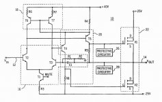
Hi, Mr. Cordell,
I wanted to ask you about this scheme. Your MosfetEC amp seems to use a sister of this scheme. It is from patent #5783970.
The goal of this patent is to get a very stable 2nd stage bias current.
While indeed this goal is achieved (through local feedback of VAS and 1st stage's current mirror), there is something that I'm not very clear.
T4 and T5's bases are driven from high impedance (collector of T6-T2).
Is this OK?
Shouldn't bases of T4-T5 is driven by low impedance (in ordinary amp, just a resistor to rail of differential legs gives low impedance to drive the VAS' base).
Attachments
- Home
- Amplifiers
- Solid State
- Bob Cordell Interview: Negative Feedback