estuart said:Hi Bob,
.... if we know the worst case impedance of a loud speaker in terms of a equivalent L-R-C network.....
The catch here Edmond is that we can either find it impossible without compromises (output coil, what if it can be shown that it degrades performance), or at best severe overkill in design and construction, that in may be most of particular application instances is not required.
Consider for example multiway active systems that not only are optimal from several points of view, but are a must in what I see an inevitable shift to wireless installations.
Rodolfo
PS Yes, I know, this goes against the DIYer's creed of freedom to mix and match at will.
estuart said:Hi Bob,
You are addressing two issues:
1. The need for an output coil.
We can only answer this question if we know the worst case impedance of a loud speaker in terms of a equivalent L-R-C network.
Cheers, Edmond
I would no go so far as to use the word "only". The idea is that we want to get good coverage of all reasonable loads, but recognize that certain simplifying assumptions are necessary, and that there will always be some "rogue" load out there that will be unusually problematic. I honestly don't think a huge amount of detail of the speaker is necessary to answer the question about whether a coil is needed, and if so how big. Most of the wiggles in the speaker impedance are at relatively low frequencies (below 20 kHz, and in fact most of the time above 5 kHz or so you are just looking at a tweeter that may or may not have a pad in front of it).
Cheers,
Bob
"rogue" loud speakers
Hi Bod,
So, in other words, we, as designers of amplifiers, should just ignore these "rogue" loud speakers. I fully agree with that!
These kind of ill designed products should banned (and of course, class-heat too 🙂)
Cheers, Edmond.
Hi Bod,
So, in other words, we, as designers of amplifiers, should just ignore these "rogue" loud speakers. I fully agree with that!
These kind of ill designed products should banned (and of course, class-heat too 🙂)
Cheers, Edmond.
Re: "rogue" loud speakers
Not to be picky, but I think that the number of "rogue" speakers that would not be adequately covered by the tests I mentioned in regard to need for a coil would be very, very small. I certainly believe that battery of tests would adequately cover the electrostatics and Wilsons in regard to HF stability, as well as virtually any speaker cable not longer than 10 feet. I think, for example, that even speakers using piezo tweeters and ribbons with step-down transformers would probably be covered.
But suggestions for plugging holes are more than welcome, as that was the intention of getting the ball rolling by putting those tests up as a start.
Cheers,
Bob
estuart said:Hi Bod,
So, in other words, we, as designers of amplifiers, should just ignore these "rogue" loud speakers. I fully agree with that!
These kind of ill designed products should banned (and of course, class-heat too 🙂)
Cheers, Edmond.
Not to be picky, but I think that the number of "rogue" speakers that would not be adequately covered by the tests I mentioned in regard to need for a coil would be very, very small. I certainly believe that battery of tests would adequately cover the electrostatics and Wilsons in regard to HF stability, as well as virtually any speaker cable not longer than 10 feet. I think, for example, that even speakers using piezo tweeters and ribbons with step-down transformers would probably be covered.
But suggestions for plugging holes are more than welcome, as that was the intention of getting the ball rolling by putting those tests up as a start.
Cheers,
Bob
Re: On the need for output coils
This is quite similar to what I actually test, and I get lower overshoot without the output coil. I can repeat the test after I catch some time and then I can show scope pictures.
Bob Cordell said:For example, perhaps we can agree that the amplifier must be adequately stable into the following set of test loads:
1000 pF at the output terminals with and without 8 ohm load.
0.01 uF at the output terminals with and without 8 ohm load.
0.1 uF at the output terminals with and without 8 ohm load.
2 uF in series with 0.5 ohm with and without 8 ohm load.
In the same test, perhaps the stability template for the above conditions should be something like this:
Apply a 1 V p-p square wave at the input, bypassing the input LPF network, and view the square wave at the output, prior to the output coil (if one is used). First cycle overshoot should not exceed 20 percent. Each cycle of ringing should be half the value of the prior, starting with the peak-to-peak value of the cycle after the initial overshoot being no more than 10% peak-to-peak.
This is quite similar to what I actually test, and I get lower overshoot without the output coil. I can repeat the test after I catch some time and then I can show scope pictures.
Well, I ran the series of tests and discovered something interesting- I don't seem to need an output coil at all. Also, testing with inductors showed nothing at all, and I used some pretty nasty high Q devices you'd never find in audio equipment of any type. But...
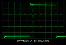
The worst case was the 2uF and no 8 ohm parallel load. (I used .33 ohms in series, because that was what was in the junk bin). Though the overall overshoot and ringing wasn't bad (I dunno, you guys tell me), the character of it disturbs me a bit. Here's the long view- the amplitude doesn't seem to matter, it always looks the same, but this was 2V/cm:
The worst case was the 2uF and no 8 ohm parallel load. (I used .33 ohms in series, because that was what was in the junk bin). Though the overall overshoot and ringing wasn't bad (I dunno, you guys tell me), the character of it disturbs me a bit. Here's the long view- the amplitude doesn't seem to matter, it always looks the same, but this was 2V/cm:
Attachments
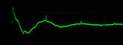
Blown up on the scope and in the computer afterwards, you can see the small spikes on each cycle. I don't like this. Do you think it means anything, or have a clue as to what causes it? BTW, my "scope camera" is me standing in front of the scope with a camera!
Attachments
Also, FWIW, I messed around with the bias, worried that stability would be bias dependent. No effect at all.
Re: Re: On the need for output coils
Good. Are you referring to overshoot prior to, or after, the coil? For purposes of stability analysis, we are more interested in overshoot and ringing as observed before the coil.
Cheers,
Bob
PMA said:
This is quite similar to what I actually test, and I get lower overshoot without the output coil. I can repeat the test after I catch some time and then I can show scope pictures.
Good. Are you referring to overshoot prior to, or after, the coil? For purposes of stability analysis, we are more interested in overshoot and ringing as observed before the coil.
Cheers,
Bob
Conrad Hoffman said:Blown up on the scope and in the computer afterwards, you can see the small spikes on each cycle. I don't like this. Do you think it means anything, or have a clue as to what causes it? BTW, my "scope camera" is me standing in front of the scope with a camera!
Hi Conrad,
I wonder if those spikes might be some kind of crossover distortion occurring in the output stage as the ringing current changes polarity. I admit that I don't see how this could be, since the square wave current would still seem to dominate and keep the other side from turning on.
If I understand correctly, this photo was small-signal square wave observed at the amplifier output with no coil, and loaded with 0.33 ohms in series with 2.2 uF?
Thanks,
Bob
Conrad Hoffman said:Well, I ran the series of tests and discovered something interesting- I don't seem to need an output coil at all. Also, testing with inductors showed nothing at all, and I used some pretty nasty high Q devices you'd never find in audio equipment of any type. But...
The worst case was the 2uF and no 8 ohm parallel load. (I used .33 ohms in series, because that was what was in the junk bin). Though the overall overshoot and ringing wasn't bad (I dunno, you guys tell me), the character of it disturbs me a bit. Here's the long view- the amplitude doesn't seem to matter, it always looks the same, but this was 2V/cm:
Just notice that your testing a SWTP Tiger amp, is it the open frame Universal Tiger?
Does it have the output protection transistors?
Does it have the correct output devices (MJ802/4502)?
I'm curious about the Tiger amps.
Edit: We had a long discussion about them back here:
http://www.diyaudio.com/forums/showthread.php?s=&threadid=41926
It would be interesting to use diff mode on your scope and look at the output stage current via R17/18 as current shunts.
Pete B.
Conrad Hoffman said:Blown up on the scope and in the computer afterwards, you can see the small spikes on each cycle. I don't like this. Do you think it means anything, or have a clue as to what causes it? BTW, my "scope camera" is me standing in front of the scope with a camera!
What was the signal source? Could D/A artifacts be the culprits? They look suspiciously regular in time (tell about the time scale in the photos).
Rodolfo
Re: Re: Re: On the need for output coils
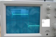
I have no output coil. And measured without input RC filter.
Regards,
Pavel
P.S.: Hope to measure again during this weekend.
Bob Cordell said:
Good. Are you referring to overshoot prior to, or after, the coil? For purposes of stability analysis, we are more interested in overshoot and ringing as observed before the coil.
Cheers,
Bob
I have no output coil. And measured without input RC filter.
Regards,
Pavel
P.S.: Hope to measure again during this weekend.
Interesting thread on the Tiger amps, and so as not to derail this one, I'll add some comments there, if I still can. IMO, Universal Tiger circuit stability has far more to do with layout and wiring, than it does with the circuit itself. I've only recently (after using mine trouble-free for 30 years!) come to fully appreciate this.
This weekend I'll look at the current in various locations and see if I can figure out what those spikes are. I have some guesses, but it's too soon to say anything. The generator used was a Wavetec 185 analog type with a 50 ohm output. I terminated the cable at the amplifier end with a 50 ohm terminator, so the edge applied to the amp was about as good as one would hope for. With and without the input network was slightly different, but the basic problem was still there. Note that the amp will happily drive a 3 uF cap without any series resistance at all. The cap sings and a polyester cap will actually heat up, but the amp does just fine and the waveform isn't much different than shown above. Still, I think it's a good idea to keep that .5 ohms (.33 in my case) in series with a 2 uF cap, so as not to abuse the output stage too badly. No, my amp has no active protection other than an output fuse. "I built it. If I blow it up, I can fix it."
The above comment about layout brings me to another idea that should be investigated. A power amp is always a compromise between low frequency wiring techniques that minimize distortion, coupling, and hum pickup, and high frequency wiring techniques that minimize inductance and loop area. While looking at my input cap which is routed on the front end of the PCB just like the rest of the circuitry, I said, "duh!, if this is for RF and slew limiting, it has to be laid out that way!" An input network should probably be done on a small piece of copper clad, right at the input connector, using small components, short leads, etc., to be sure it's truly keeping RF out of the chassis. Once you have wires traveling inside the chassis, it's too late to be worrying about RF and sharp edges.
Yes after simulating the Tiger and finding it to have reasonable gain and phase margin small signal, I came to the conclusion that it must be layout, wiring, and large signal considerations.
It is interesting that many test stability at small and mid signal levels, however we know that these BJT outputs are slow (very) coming out of saturation and therefore large signal with clipping is probably worst case, or at least different.
I'm not suggesting you try it with the Tiger since, in my experience, it is likely to blow up.
Yes, we should probably move to the other thread. I did a quick simulation and provided a zip files here, for both the original and just the output with newer devices:
http://www.diyaudio.com/forums/showthread.php?s=&threadid=93637
I've built many Tigers over the years, but I've not had an exact Universal Tiger for many years. I only just got a single Universal Tiger recently, that does not work, has the wrong output transistors, and is the version with output protection. I don't know when I'll have the time to repair it so that I can compare it to the simulation.
Pete B.
Conrad Hoffman said:....
This weekend I'll look at the current in various locations and see if I can figure out what those spikes are. I have some guesses, but it's too soon to say anything. ...
If - as I guess it is - there is a CFP output, and moreover uses MOSFETS, take a look at the gate (base) - rail voltage and see if there is an abrupt transition coincident with the spike.
Rodolfo
Firstly Bob,
Your post #837, starting all this. To my mind an admirable summing up (if one can say that regarding a start!) - as is usual with all your contributions.
My general small addition would be that one must not loose sight of the practical situation. One is not designing a "perfect" amplifier - bandwidth-wise that is not too much of a task; look at scope channel amplifiers! My point: Most things are a compromise. You clean up every little bit, and you sacrifice something somewhere else. Designing for audio one must "make use" of that "limitation" to advantage. My priority would be: Design as good as you can for audio conditions (stability, high order harmonics, slew rate, blah blah blah), then, if anything undesirable remains (hopefully outside the audio band), try take care of that - coil, capacitor, whatever [only not snake oil - er, "snake coil", perhaps, in some situations??].
Yes, I agree that output inductors are often piously used (perhaps even then a blessing, if unintended!). In my own designs I found them an aid to improved stability in what I hoped were sober practical considerations, including some worst case. It is interesting that PMA (was it you?) found his design better without it - so be it then for him. Though not the topic any longer, I made sure that any effect was above the audible range, and for me that is that.
Perhaps of interest, where I used a fully complementary output topology, I found advantage in taking the global NFB off the driver stage (just before the final) as far as stability was concerned into severely capacitive loads - small increase in distortion, outweighed by stability improvement.
Conrad,
I would not worry about those small perturbations. (I know the feeling, but don't be a perfectionist like me - as divorced from realism - it makes life awful!) If your amplifier is stable under all conditions that you can think up, all these can do (very academically) is cause overload some 0,5dB before the real overload - big deal! But as DIYer I also investigated where I had similar appearances, and I found them on the power rails, different at different parts of the layout, even different depending on where I earthed the scope probe. An extremely small capacitor somewhere sometimes helped, but as said, necessary??
Regards
As usual, other things have taken priority, so I've plugged the amp back in the system and will just listen to it for a while. Pete, appreciate your work on the tiger circuit, and I'll have to study it a bit more. I've half a mind to do a new board layout, but then I'd want to redesign the amp from the ground up (pun intended). John, I think you make a very good point, though from an engineering point I always tell people "investigate and explain all anomalies". It can save a lot of embarrassment down the road, but in this case I don't think any audio signal is going to perturb the thing.
Regards,
Conrad
Regards,
Conrad
- Home
- Amplifiers
- Solid State
- Bob Cordell Interview: Negative Feedback