roender said:Sorry guys, I made a drawing error.
This is the correct way and it's working, I just tested and it is stable.
Hi Roender,
If you send me the spice models of the output devices and drivers, I'll have a closer look at your design.
Regards,
Hi Estuart,
Would be nice to confirm my calculation, thank you
All SPICE models are freely available
http://www.onsemi.com/PowerSolutions/supportDoc.do?type=models&rpn=NJL0281D
http://www.onsemi.com/PowerSolutions/supportDoc.do?type=models&rpn=NJL0302D
http://www.onsemi.com/PowerSolutions/supportDoc.do?type=models&rpn=MJE15035
http://www.onsemi.com/PowerSolutions/supportDoc.do?type=models&rpn=MJE15034
roender said:Hi Estuart,
Would be nice to confirm my calculation, thank you
..........................
All SPICE models are freely available
Thanks, tomorrow I'll work it out.
Regards,
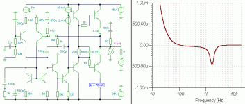
What do you think about this FB compensation methode?
Hi Roender,
Nice design and very stable, no ringing or overshoot.
Here are a few results of my simulation:
THD20 = 10ppm @ 60W.
Slew Rate = 24V/uS.
To keep it stable, shunt compensation by means of C8 and C9 seems indispensable.
Cheers,
Hi Roender,
Nice design and very stable, no ringing or overshoot.
Here are a few results of my simulation:
THD20 = 10ppm @ 60W.
Slew Rate = 24V/uS.
To keep it stable, shunt compensation by means of C8 and C9 seems indispensable.
Cheers,
Thank you Edmond
Your results are very close to mine. You used LTSpice?
Now, I try to make C8/9 as small as possible to make slew rate over 30V/us
Can you simulate negative/positive PSRR, please?
Your results are very close to mine. You used LTSpice?
Now, I try to make C8/9 as small as possible to make slew rate over 30V/us
Can you simulate negative/positive PSRR, please?
roender said:Thank you Edmond
Your results are very close to mine. You used LTSpice?
Now, I try to make C8/9 as small as possible to make slew rate over 30V/us
Can you simulate negative/positive PSRR, please?
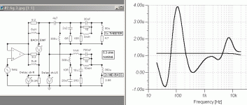
Hi Roender,
When C8/9=82pF your amp is getting unstable. So, try to increase the standing current of the 2nd diff. stage, choose for example R18=47Ohm (and adjust R35!). But now, you amp gets unstable again, so I increased the 150pF cap (C25 in my schematic) to 180pF.
Figures are quite better:
THD20 = 4.3ppm ans SR = 30V/uS.
PSRR wrt V+ is ca. -100dB (up to 10kHz)
PSRR wrt V- is -87... -98 db (up to 10kHz)
Cheers,
BTW, I do have LTSpice, but I only use it as viewer of asc files.
As a matter of fact I prefer Micro-Cap.
Thank you
Your assumptions are correct but I prefer another way to decrease those caps.
I would try to put small resistors, 10-20ohm, in series with emitters of VAS LTP ...
Your assumptions are correct but I prefer another way to decrease those caps.
I would try to put small resistors, 10-20ohm, in series with emitters of VAS LTP ...
While away I have been trying to come up with some way of getting around the *established* thinking that members here keep hitting me with.
I know what you are saying, but if I try to follow your rules and your limited acceptance of definitions I cannot communicate my thoughts.
My last sim was to show that NFB amplifier error sensing affects the differential wrt source input. This fact is probably already appreciated - but has this been thought about, because this causes a variation in group delay at AF, such that even input filters end up having their group delays modified by loudspeaker reactivity.
Within amplifiers I have tried all sorts of clever sub-loop NFB arrangements enclosed by a global loop, and they don't work.
The more active devices enclosed by any global NFB loop the more un-natural reproduction becomes no matter how high the steady sine linearity.
This is why I stuck with the JLH class-A layout because the NFB is merely a common base driving a Darlington common emitter arrangement, thus virtually a single stage at the higher frequencies where the NFB must act in order to correct at AF.
I have for many years examined NFB AF amplifiers by observing the output stage when reverse driven, thus I have always tried to minimise both the amplitude and time to settlement for error, but before today I never thought of examining the group delay of an output stage's response to loudspeaker generated back-EMF.
A modified 'blameless' type circuit was shown above with two additional components around the VAS. Mike and I showed that the inner loop showed a degree of peaked response. This response will improve 'thd' at say 10kHz - but - for steady sine only - not loudspeaker music reproduction - though the Sims do not show this !!!
See from this attachment what that arrangement does to group delay for the damping response.
Where group delay varies, then all coincident waveform amplitudes become affected due to fractional voltage superimposition, and I am actually quite shocked to see such a large variation where our hearing is so sensitive.
I know from years of Simulation that this is due to a phase shifted damping response due to bandwidth control within the global NFB loop - and yet SO MANY current designs still do it !!!
All the books, maths, lectures etc. ( ie. the rules of established thinking ) do no more than take students for a plod down the well trodden path; they could so easily be PREVENTED from enjoying the beauties of the scenic route !!!
Cheers .......... Graham.
Attachments
Graham Maynard said:While away I have been trying to come up with some way of getting around the *established* thinking that members here keep hitting me with.
I know what you are saying, but if I try to follow your rules and your limited acceptance of definitions I cannot communicate my thoughts.
My last sim was to show that NFB amplifier error sensing affects the differential wrt source input. This fact is probably already appreciated - but has this been thought about, because this causes a variation in group delay at AF, such that even input filters end up having their group delays modified by loudspeaker reactivity.
Within amplifiers I have tried all sorts of clever sub-loop NFB arrangements enclosed by a global loop, and they don't work.
The more active devices enclosed by any global NFB loop the more un-natural reproduction becomes no matter how high the steady sine linearity.
This is why I stuck with the JLH class-A layout because the NFB is merely a common base driving a Darlington common emitter arrangement, thus virtually a single stage at the higher frequencies where the NFB must act in order to correct at AF.
I have for many years examined NFB AF amplifiers by observing the output stage when reverse driven, thus I have always tried to minimise both the amplitude and time to settlement for error, but before today I never thought of examining the group delay of an output stage's response to loudspeaker generated back-EMF.
A modified 'blameless' type circuit was shown above with two additional components around the VAS. Mike and I showed that the inner loop showed a degree of peaked response. This response will improve 'thd' at say 10kHz - but - for steady sine only - not loudspeaker music reproduction - though the Sims do not show this !!!
See from this attachment what that arrangement does to group delay for the damping response.
Where group delay varies, then all coincident waveform amplitudes become affected due to fractional voltage superimposition, and I am actually quite shocked to see such a large variation where our hearing is so sensitive.
I know from years of Simulation that this is due to a phase shifted damping response due to bandwidth control within the global NFB loop - and yet SO MANY current designs still do it !!!
All the books, maths, lectures etc. ( ie. the rules of established thinking ) do no more than take students for a plod down the well trodden path; they could so easily be PREVENTED from enjoying the beauties of the scenic route !!!
Cheers .......... Graham.
Hi Graham,
You're not the only one whose measures amplifiers with back-drive and sees value in it. I do as well. One of my favorite tests is to back-drive it with a twin-tone signal to reveal IM that is largelt the result of crossover distortion, absent other distortion that is caused by large voltage swings in the VAS. The absence of large voltage swings also greatly enhances the useable dynamic range of the spectrum analyzer.
Cheers,
Bob
Yes, and the technique of allowing one channel to drive the
other allows simple observation of notch distortion for DIYers
who don't have a distortion analyzer. Helps a lot with bias
adjustment, and I wrote this up in my Mosfet HK12 article.
😎
other allows simple observation of notch distortion for DIYers
who don't have a distortion analyzer. Helps a lot with bias
adjustment, and I wrote this up in my Mosfet HK12 article.
😎
Hi Nelson,
I guess from what you say - that minimising error via reverse drive testing does actually minimise audible reproduction distortion, it is just that I have not yet come across anyone actually stating this.
Hi Bob,
With forward global NFB controlled drive the output of most decent amplifiers will follow input well within 100 nanoseconds, but when load current at output leads input voltage, a fractional voltage error will arise when the amplifier's internal open loop has been 'slowed' to ensure global stability, which class-AB crossovers merely exacerbate.
Twin tone reverse driving will most certainly show up whether output terminal damping is coherent or phase shifted with frequency.
Cheers ......... Graham.
Graham Maynard said:I guess from what you say - that minimising error via reverse drive testing does actually minimise audible reproduction distortion, it is just that I have not yet come across anyone actually stating this.
Minimizing error is just that. Since much of the error in a power
amplifier is dependent on output current, you can see a lot of it
by having the output stage absorb current. It is not, however,
a different form of distortion, just another way of looking at it.
😎
Graham Maynard said:My last sim was to show that NFB amplifier error sensing affects the differential wrt source input. This fact is probably already appreciated - but has this been thought about, because this causes a variation in group delay at AF, such that even input filters end up having their group delays modified by loudspeaker reactivity.
....................
I have for many years examined NFB AF amplifiers by observing the output stage when reverse driven, thus I have always tried to minimise both the amplitude and time to settlement for error, but before today I never thought of examining the group delay of an output stage's response to loudspeaker generated back-EMF.
I am perhaps committing a brutal sin by daring to comment on something without having read the hundreds of other posts here, but I caught this line of thought.
The above is utterly important, and I must also agree with what Graham seem to say about conventional thinking, without implying anybody specific. I have also done my modest simulation in this manner, and discovered some quite sobering glitches in my own line of thought. If one is to be blamed for this sort of thinking, then I seem to be in good company.
Graham,
If not mentioned before in this thread, you are probably aware of the analysis published by Prof Otala in an article on the amplifier-loudspeaker interface (Wireless World, Nov.-Dec. 1980), which is also illuminating.
Regards.
Hi Johan,
Thanks for your feedback. I had to pass on my 1954-1994 collection of WW / E+WW due to space encroachment; also the most recent EWs have been going straight in the bin due to uninspiring content.
So it is likely I saw the Prof Otala article at the time, though just do not recall it specifically at the moment.
Hi Nelson,
'Just another way of looking at it' - indeed so.
I chose to stick with trying to explain from basic circuit current flows wrt voltage, but always found my interpretations challenged as if I did not understand fundamentals.
____________________________________________________
From loudspeakers we all know that transient responses are different to steady sines; thus any amplifier loading response is similarly different.
First cycle audio voltage waveforms especially, passing through RC filters and when driving C+L+R loudspeakers, cannot be assumed to pass with coherent group delay because, by definition, group delay in time is based upon measuring the steady voltage waveform delay wrt the zero voltage axis after passage.
When loudspeaker back-EMF causes leading current flow wrt to voltage drive, the 'group delay' can become negative.
I illustrated this by computer simulation with a virtual loudspeaker causing group delay to become negative in my 2004 EW writing, and was sumarily castigated for showing 'voltage waveform arriving at a louspeaker before it left the amplifier'; a resultant which can actually arise in the real world too. Thus amplifier circuitry can/does cause hf waveform distortion wrt the fundamentals we hear when the loudspeaker system is reactive at those fundamental frequencies, this being on an independent - per channel - basis which can affect the stereo image.
C+L+R filters, networks and loudspeaker drivers/cabinets do not behave like propagation/waveguide blocks prior to steady wave development ( ie. when the waveform is music ) and where this impacts upon amplifier capabilities, these 'conventionally linear' components can generate extremely non-linear interaction responses within 'NFB linearised' amplifiers, esp when the natural open loop response is rendered inadequate at AF by stabilisation componentry.
Actually EW has failed to publish my letters written in response to such challengers who clearly failed to realise that 'linear' circuitry can cause distortion within NFB amplifiers, due to the varying group delay at the output sensing node wrt both the loudspeaker terminal voltage and original source voltage. Maybe the new editor is incapable of this type of 'imagineering' too. The old editor - Phil Reed - understood what I had started to explain, but, due to 'conventional' clamour, it will now never be completed.
An amplifier like some of Nelson's producing a purely current output wrt voltage input, is thus not going to generate NFB induced reactions due to loudspeaker characteristics, but then the loudspeaker itself will resond differently when compared to voltage drive. Thus different loudspeaker types produce different responses with the two different amplifier types, and not all types of loudspeaker are equally suitable to both types of amplifier.
Of course 'pure voltage follower' output stages will not generate the same NFB (SS) sound within their class-A operating range either if the NFB loop does not enclose them, though followers running in complementary class-AB might still pose some loudspeaker back-EMF related problems.
And there is always;-
http://www.diyaudio.com/forums/showthread.php?s=&threadid=42259&highlight=
though my choice has been to use NFB, but specifically minimise load current induced voltage reactions in time.
Above I wrote that I had not thought of testing 'reverse' group delay for amplifiers, though I have done it on my own recent circuits. It is just that mine don't react like that in post#788 above, so I did not think any more of it in relation to circuits I was not interested in.
Cheers ....... Graham.
Negative group delay is as possible as meeting king Arthur and knights of the round table tommorow IMHO.
Johan Potgieter said:
I am perhaps committing a brutal sin by daring to comment on something without having read the hundreds of other posts here, but I caught this line of thought.
The above is utterly important, and I must also agree with what Graham seem to say about conventional thinking, without implying anybody specific. I have also done my modest simulation in this manner, and discovered some quite sobering glitches in my own line of thought. If one is to be blamed for this sort of thinking, then I seem to be in good company.
Graham,
If not mentioned before in this thread, you are probably aware of the analysis published by Prof Otala in an article on the amplifier-loudspeaker interface (Wireless World, Nov.-Dec. 1980), which is also illuminating.
Regards.
Hi Johan,
These are very long threads, so don't feel guilty about jumping right in.
You are right about the need for unconventional thinking. It is often closely linked with creativity and innovation. We often hear the story about someone who invented something because someone forgot to tell him it wouldn't work.
Its also important, however, that unconventional thinkers review their conclusions with a diligent and open thought process, questioning their own conclusions just as others would, and doing lots of consistency checks. Its very good to think with a clear head in the absence of what has gone before, and not be self-inhibited by that sort of thing. However, once the new theory or viewpoint is crystalized, it is important to test it against "conventional" thinking to see where the differences are and if they can be explained by new insights that are valid. This is where some "unconventional" thinkers fall down.
Your mention of Otala is relevant here. I think he could be considered an unconventional thinker. Indeed he was one of the smarter and well-informed unconventional thinkers. Unfortunately, he had some blind spots. While much of what he asserted was technically correct in some respects, he reached bottom-line conclusions that were simply wrong and have long since been disproved.
He also blissfully ignored much of what went before. He essentially re-invented the concept of slew rate limiting and re-named it. Slew rate limiting was known and well-socialized among the engineering community since at least World War II, when it was used to describe the maximum rate at which a feedback-controlled gun could move. It is remarkable that he never mentioned the term once in his early papers until after others pointed out that what he was describing was slew rate limiting. Some say it was a language barrier, but he was actually very well-spoken, and I don't believe it was the case. I think it was just a blind spot.
He went on to wrongly conclude that large amounts of negative feedback were the cause of TIM, and that the solution was low feedback or no feedback. In so doing, he misled an entire generation of audio engineers. He also proposed other forms of distortion that were supposedly caused or exacerbated by NFB, such as PIM and IIM, and was again proven wrong when others carefully examined his results. Indeed, often the very measurement techniques he proposed for measuring these new forms of distortion were what proved him wrong. See my papers on TIM, PIM and IIM on my website at www.cordellaudio.com. However, his work was not without value. Even though his bottom-line assertion that NFB was evil was wrong, he caused a debate that made people work hard to understand the issues he was raising, and as a result a lot of people gained valuable insights.
Cheers,
Bob
Okay Darkfenriz,
Using your understanding, please explain to me the simulation in post#788.
Remember - group delay is after a full cycle where current can lead voltage, and the plot is thus a steady response measurement at the frequency shown on the axis.
During an initial response ( first cycle ) the voltage leads the current until modified by reactivity; we are not thinking about pure capacitance circuits here, so voltage always leads current at outset.
Here's another. A simulated perfect amplifier driving R and a virtual LS via series output choke//resistor. Flat group DELAY with the resistor; group delay due to LS varies +/-2uS wrt to R voltage, and actually becomes negative due to LS resonance.
This can affect crossover in class-AB circuits also NFB loop responses. Room length cables have similar inductance in series with their low R. Thus LS terminal V is not coherently corrected wrt source voltage at the amplifier's input socket.
C+L+R circuits cannot be viewed as if radiation waveguides or propagation mediums.
Cheers .......... Graham.
Attachments
darkfenriz said:Negative group delay is as possible as meeting king Arthur and knights of the round table tommorow IMHO.
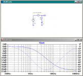
Hi Adam,
If one were to consider a constant group delay with frequency, then a negative group delay would imply a non-causal system which is of course unrealizable. But it's quite easy to give an example of a simple circuit which at some frequencies will have a negative group delay. All that's required is that the slope of phase vs. frequency be positive at some frequency or range of frequencies.
The simple circuit below has a negative group delay at frequencies above about 5 kHz.
Attachments
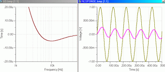
Hi Andy,
Att. The group delay for your circuit, and the response we all know.
There will be those who say you musn't test with a suddenly starting sine, but failing to do so merely covers up the problem.
A debate could also be about what degree of group delay change becomes audible at any frequency, though where it becomes important is with loudspeaker loads and NFB loop controlled voltage amplifiers; esp. class-AB.
Cheers ....... Graham.
Attachments
- Home
- Amplifiers
- Solid State
- Bob Cordell Interview: Negative Feedback