JLH = John Lindsey Hood and not Hiragas amp.
Output impedance for the le Monstre is a few Ohms.
Sigurd
Output impedance for the le Monstre is a few Ohms.
Sigurd
lineup said:
Lumba.
You should really have a read on a Nelson Pass paper from 2005.
.. unless you have already studied this great paper
See his investigation on feedback factor, in 4 rather classical amplifiers.
JLH is one of them.
I have attached a little teaser image.
Go download at www.passdiy.com
The PLH Amplifier: The classic JLH - Pass style
Then you thank me, lineup, for telling.
But most of all give a nice thought to Our One and Only Nelson.
For doing a good audio work .. and sharing it with us
Lumba,
I have attached my le monstre file. To use it in MicroCap
just rename the file to *.cir
and you can play with it, and also add your own ideas
as you have another 25 components to add to my CIR before
the evaluation version says stop.
Enjoy!
Sigurd
I have attached my le monstre file. To use it in MicroCap
just rename the file to *.cir
and you can play with it, and also add your own ideas
as you have another 25 components to add to my CIR before
the evaluation version says stop.
Enjoy!
Sigurd
Lumba Ogir said:HKC,
The bias currents:
Input 1mA
Output 500mA
Sigurd,
nice to have you around. Thanks again.
Would this work?
Attachments
Lumba Ogir said:HKC,
The bias currents: Input 1mA Output 500mA
Hello there.
Looks like another guy did the job for me. So I wont have to simulate and find out feedback factor
Now.
Almost any classical amp, is around in several variants. Often with some exchanged, 'more modern' transistors. We see designers make Revised versions. This is not the first, original version. But often improved in some way.
I refer to such a new variant. And this is what I will do, further in this topic.
Because, if I built Le Monstre, there is no way I would be able to use the original devices, anyway.
It is this new version I mean. With 2SK246 / 2SJ103 as good new substitute JFET pair.
Hiraga Le Monstre - Suggested new transistor substitutes.
Even if the numbers, currents can/will be different for the original, my advices, as method, can be used for any Le Monstre version. I mean what factors will determine the idle currents in output stage.
As I mention in a previous post
Also, without knowing the original current,
I suggested an initial value of 1.0 Ampere for 8 Ohm speakers.
It seems a good value to start with .. and can be increased later, when we got everything working and want to try with more current.
Sigurd suggests 2.5 A, which seems a bit high to me. Of course for speaker Z dips (downto 4-5 Ohm) and for 4 Ohms speakers we can really need this high currents.
What me and Sigurd agree on, is that the original 0.5/0.6 Ampere is a bit low. At least for modern speakers and operating at the higher end of the power (say 5-7 Watts RMS/8Ohm), and that peformance probably would be better with a bit more current.
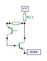
Lumba Ogir said:Would this work?
Can you explain your idea more, Lumba.
I do not get it from your image.
lineup
lineup,
It is an attempt to linearize the driver by increasing its emitter resistance.
You do not know.I would think that this 2SK246 / 2SJ103 version is really by Hiraga. But I do not know.
It`s fine...for a while.Sigurd suggests 2.5 A, which seems a bit high to me.
I blame the software.Can you explain your idea more, Lumba. I do not get it from your image.
It is an attempt to linearize the driver by increasing its emitter resistance.
Lumba Ogir said:lineup,
I blame the software.
It is an attempt to linearize the driver by increasing its emitter resistance.
I see.
Yeah, the optimal value can be different, at different output levels + different loads (normally I do not use pure resistors for load, when I listen to my amps)
Nelson Pass puts it like this:
This means an optimal resistance to set the 'best' average current of operation.There is a sweet spot
for a every transistor in a given circuit.
For a special job to do.
Such a resistor is almost always a compromize.
For the best operation at low levels of output and a high.
For normal (1kHz)audio frequencies music and for higher frequencies.
When designing such a blameless, good compromize amplifier
that will work with good quality in many situations,
it may require a bit of tweaking up & down, until finding 'the optimal compromize'.
lineup
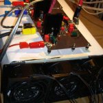
solen lyser här i norra sverige nu, Lumba!I actually have used 2.8 A at 20V rails for a long time and as long as one has proper cooling, there are no problems.
I do use a 350mm long heatsink with 3x 80mm mains powered fans for a stereo setup. See attached image.
I tried your idea with degenrating the drivers, Lumba, but distortion increased.
SIgurd
I do use a 350mm long heatsink with 3x 80mm mains powered fans for a stereo setup. See attached image.
I tried your idea with degenrating the drivers, Lumba, but distortion increased.
SIgurd
Lumba Ogir said:lineup,
You do not know.
It`s fine...for a while.
I blame the software.
It is an attempt to linearize the driver by increasing its emitter resistance.
Attachments
Sigurd,
lineup,
start planning for the implementation!
That`s a very good sign, THD rises as it should.I tried your idea with degenrating the drivers, Lumba, but distortion increased.
lineup,
start planning for the implementation!
Re: "Le Monstre" - working
Hi Daniel
Would you please tell where did you get the original transistors for Le Monstre? I tried to order from MCM Electronics but they do not ship parts outside USA.
Best Regards
danieljw said:hello people
I just built "Le Monstre" using origional transistors
tried it last night.... I have to say the amplifier sounds really really good
has any one else tried it ???
pictures to come.
-Dan
Hi Daniel
Would you please tell where did you get the original transistors for Le Monstre? I tried to order from MCM Electronics but they do not ship parts outside USA.
Best Regards
Sigurd Ruschkow said:500m - 600mV over 1 Ohm is the Ib value,
which is too little, IMO, to get 8W into
8 Ohms. Into 4 Ohms you will only have half of what you get at ( Ohms (into class A).
I have played with the Hiraga le Monstre and am running at
2.5A idle current and that at about 20V rails using 0302/0281 Onsemi transistor. Needs some heavy duty fan cooling
Hi Siqurd, Lumba & Lineup thank you guys for giving your comments about idle current. I would like to set the current @ 1A as suggested for 8 Ohm load speakers so in this case, do I need to change the value of the emitter resistors of the power transistors? If yes, what is the resistors value would be?
Best Regards
HKC said:
I would like to set the current @ 1A as suggested for 8 Ohm load speakers so in this case, do I need to change the value of the emitter resistors of the power transistors?
If yes, what is the resistors value would be?
lineup said:
The procedure for seeting like 1 A current in output, can take some time.
For 8 Ohm speakers, this would be my initial current setting.
When you have 1 Volt DC across both 1 Ohm resistors, you will have 1 Ampere running.
What factors effects (most) how much current/voltage across 1 Ohm resistors?
Several things:
====================================
1. What JFETs you use.
And different exemplars of same 2SK170 /SJ74 can differ.
2. THe potentiometer.
50 OHM or (47) pot = most current,
100 Ohm pot = normal
220 Ohm = less current.
3. Value of 1 k Ohm's resistors.
Higher value = more ampere in output.
Lower value less current.
====================================
Visit Dan's homepage, like he said. In previous post.
I am also sure he can guide you well how you should do, to trim and adjust Le Monstre. in a safe and good way.
... because if you are unlucky ... you may do a BurnOut .. at first Power on

You have already forgotten my post
I tell 3 things that will effect How much current in output.
1)
- I suppose, you use GR variants of JFETs.
- They will suit the original schematic best.
With something like ~ 1.7 mA in input stage.
Across 1 kOhm resistors at Drain side.
Measure voltage across those resistors, without adding the output stage.
The output stage is:
(2SB716 / 2SB756 / 2SD844 / 2SB754 transistors.)
Balance with trimpot until about same voltage across both positive and negative 1 kOhm resistor.
Trimpot center should be attached to GND, when you have not attached output stage.
1 Volt across 1 kOhm = 1 mA
1.7 Volt across 1 kOhm = 1.7mA, this is the value that should give like 1 Ampere across 1 Ohm
(for the schematic with 2SK246 / 2SJ103, I refered to earlier, we should use 2SK170BL / 2 SJ74BL .... something like 4 mA in input, across 390 Ohm resistors in DRAINS)
2)
The potentiometer, should be chosen to give like 1 - 2 mA in your JFETs.
In the original 100 Ohm trimpot.
If you want more current ( measure ), then you may have to change to 47 Ohm trimpot.
If you want less current, change to 220 Ohm trimpot.
3)
When you have like 1-2 mA. Or better 1.7 - 1.8 mA.
Then, you could temporarily replace both 1 kOhm resistors
with 2k2 trimpots.
Start with a low value in them pots, before you power on.
Then you can carefully increase the trimpots resistance value, on both sides.
While all the time balance for 0 Volt at output terminal.
When you have reached 1 Volt across BOTH 1 Ohms resistors,
you can replace those two 2k2 potentiometers with suitable resistors.
With closest resistor value.
I suggest you should NOT change the 1 Ohm resistors, in output
It is nice to know that 1 Volt is = 1 Ampere. For control!
-------------------------
So, sum is:
1. Try to get 1-2mA in input 2SK170GR / 2 SJ74GR (or 2SK170BL / 2SJ74BL )
This you do with use the best suitable potentiometer in '100 Ohm' place.
Can be 47, 100, 220 trimpot.
2.. Change the 1 kOhm resistors value
(1.2 kOhm will give more current in output, 820 Ohm will give less)
until you get 1 Volt across BOTH 1 Ohm.
Balance all the time with trimpot.
lineup
-------------
Ps.
Hiraga was clever. He has chosen 1 Ohm and 1 kOhm resistors
to make it easy for us.
1 Ohm and 1 kOhm values we often have at home. We can buy many of those values, and get them for lower price.
And this way we can easy measure.
1 Volt into 1 Ohm = 1 Ampere, 0.6 Volt = 0.6 A.
Same with 1 kOhm:
1.00 Volt = 1.0 mA, 1.70 Volt = 1.7 mA, 2.00 Volt = 2.0 mA
HKC said:Hi Lineup
Yes I overlooked your post. I am sorry for that.
I need to take some time to go through all the details. Once again thank you for sending the information, very appreciated.
Have a great weekend.
Yes, it has been many other posts here. Which is good when people are interested
There is nothing so bad as when nobody posts, when you need advice.
I wrote my last post very quickly.
But hope you can get the procedure I would use.
--- Your first setup should be without output stage.
When you get 1.7 Volt across BOTH those '1 kOhm' resistors ( using 820, 1000 or 1200 Ohm)
Then you may attach output stage.
Without loudspeaker, PLEEEAAASEEEE
Instead you HAVE TO USE a dummy load power resistor.
One big 5-10 Watt power resistor, in the place of Speaker.
The value can be like 10 - 22 Ohm.
Take what you have.
also first speaker you attach to an amplifier under construction
..
 should be some old cheap one, something you wont miss much,
if it get destroyed
Re: Re: "Le Monstre" - working
Hello HKC,
Wow this thread got interesting all of a sudden !
The power supply uses 1 LM338K per rail. and is +/- 12V d.c.
The transistors were sourced by another diyaudio member via ebay.
If you do a search in ebay you may be able to get some still.
If not I have some of the transistors left.
-Dan
HKC said:
Hi Daniel
Your Le Monstre link is very interesting.
According to the power supply schematic. You use 2 LM338K for both of the upper and lower section. As far as I know, LM338K is a positive regulator therefore, should there be 1 LM338K and another negative regulator to form the regulator section instead of 2 LM338K? In addition, the two voltage rails are specified as -12V. Is this typing error? I think they should be +12V & -12V respectively. Correct me if I am mistaken.
Back to the Le Monstre schematic. Is the 100 Ohm trim pot use to adjust the voltage at output? Please advice.
Thanks & regards
HKC said:
Hi Daniel
Would you please tell where did you get the original transistors for Le Monstre? I tried to order from MCM Electronics but they do not ship parts outside USA.
Best Regards
Hello HKC,
Wow this thread got interesting all of a sudden !
The power supply uses 1 LM338K per rail. and is +/- 12V d.c.
The transistors were sourced by another diyaudio member via ebay.
If you do a search in ebay you may be able to get some still.
If not I have some of the transistors left.
-Dan
Lumba - what are your thoughts regarding inserting degeneration resistors for the?
Wanna go OL?
Sigurd
Wanna go OL?
Sigurd
Lumba Ogir said:Sigurd,
That`s a very good sign, THD rises as it should.
lineup,
start planning for the implementation!
- Home
- Amplifiers
- Solid State
- Hiraga "Le Monstre"