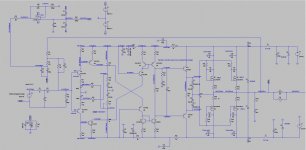
For comparison here you have the RCP130 KRISHNA FETSYM EVO9.22 schematic.
In this case the capacitor C8 (3pF) is critical both for stability and THD. Using 5pF doubles THD.
I believe that a circuit dependent of such a low value capacitor is risky to say the least. Any circuit parasitic capacitance might compromise stability.
In this case the capacitor C8 (3pF) is critical both for stability and THD. Using 5pF doubles THD.
I believe that a circuit dependent of such a low value capacitor is risky to say the least. Any circuit parasitic capacitance might compromise stability.
Attachments
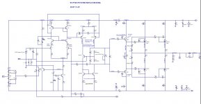
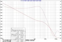
In this case (Krishna) I also have good stability numbers 101° PM and 14dB GM but the phase "dances" a while and does not present always the same value.
Max OLG @ low frequencies is also lower so I preview a less than optimum bass reproduction in this case.
VAS shunt caps C6 C10 are 47p and this is optimized for a more stable phase response and lower THD.
Increasing C8 to a more reasonable value (5p) seriously compromises THD.
It might work and maybe I will return to this design but not right now.
Attachments
SHIVA LUXMAN
I always wondered how a cascoded VAS would sound and I redirected myself to the Luxman 120 schematic that uses hawksford cascoded VAS.
I chose this one because of it's good sound and also because OS told me that the cascoded VAS works better with symetrical VAS.
After several simulations I finally got the circuit working.
I will call it the RCP130 EVO46.8 SHIVA LUXMAN.....
Attachments
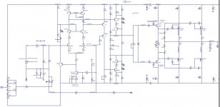
As the Shiva has a symmetrical VAS, clipping is soft so no need for clamping diodes.
I decided to keep the original compensation with the Zobel's R11 C17 and R15 C18 although the values were modified for my implementation.
Stability is acceptable with 73° PM and 21dB GM... some work needs to be done to level phase and maybe increase PM.... difficult without increasing THD
I decided to keep the original compensation with the Zobel's R11 C17 and R15 C18 although the values were modified for my implementation.
Stability is acceptable with 73° PM and 21dB GM... some work needs to be done to level phase and maybe increase PM.... difficult without increasing THD
Distortion @ 1khz 50W into 8ohm is not bad:
Harmonic Frequency Fourier Normalized Phase Normalized
Number [Hz] Component Component [degree] Phase [deg]
1 1.000e+03 2.828e+01 1.000e+00 -0.22° 0.00°
2 2.000e+03 4.721e-05 1.669e-06 -2.45° -2.22°
3 3.000e+03 9.241e-06 3.268e-07 -90.55° -90.32°
4 4.000e+03 3.655e-06 1.292e-07 -4.07° -3.84°
Total Harmonic Distortion: 0.000171%(0.000210%)
With 20khz 50w into 8ohm is also acceptable:
Harmonic Frequency Fourier Normalized Phase Normalized
Number [Hz] Component Component [degree] Phase [deg]
1 2.000e+04 2.823e+01 1.000e+00 -4.56° 0.00°
2 4.000e+04 9.557e-04 3.386e-05 -5.64° -1.08°
3 6.000e+04 2.514e-04 8.907e-06 -61.73° -57.17°
4 8.000e+04 1.084e-04 3.839e-06 -31.92° -27.36°
Total Harmonic Distortion: 0.003522%(0.006123%)
Harmonic Frequency Fourier Normalized Phase Normalized
Number [Hz] Component Component [degree] Phase [deg]
1 1.000e+03 2.828e+01 1.000e+00 -0.22° 0.00°
2 2.000e+03 4.721e-05 1.669e-06 -2.45° -2.22°
3 3.000e+03 9.241e-06 3.268e-07 -90.55° -90.32°
4 4.000e+03 3.655e-06 1.292e-07 -4.07° -3.84°
Total Harmonic Distortion: 0.000171%(0.000210%)
With 20khz 50w into 8ohm is also acceptable:
Harmonic Frequency Fourier Normalized Phase Normalized
Number [Hz] Component Component [degree] Phase [deg]
1 2.000e+04 2.823e+01 1.000e+00 -4.56° 0.00°
2 4.000e+04 9.557e-04 3.386e-05 -5.64° -1.08°
3 6.000e+04 2.514e-04 8.907e-06 -61.73° -57.17°
4 8.000e+04 1.084e-04 3.839e-06 -31.92° -27.36°
Total Harmonic Distortion: 0.003522%(0.006123%)
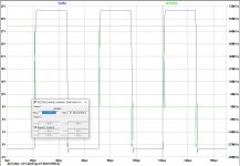
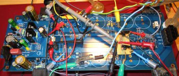
Strong square waves at 20khz show a slight overshoot but SR seems very good even with the input filter in place.
SHIVA SQUARE
SHIVA SQUARE 0.5V input
The slight "undershoot" can be cured by reducing C4 to 10p
SHIVA SQUARE 0.5V input
The slight "undershoot" can be cured by reducing C4 to 10p
Attachments
Last edited:
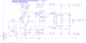
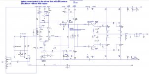
Final design for the LIN topology RCP130 BRAHMA EVO44.2554.
I am now using the EFA Mirror.
To equalize collector voltages in the mirror Q13 Q14, I sized the helper bjt emitter resistor so it's base current is the same as Beta enhancer Q16 base current.
D17 baker clamp is effective but affects THD so I will leave space for it but as an option.
Q5 current limiter bjt does not affect THD and is also effective but it's operation depends on the VAS emitter resistor. So if we need to change R63, Q5 must also be revisited..... will leave it as an option.
With the helper bjt in the IPS mirror with carefully selected emitter resistor I get similar collector voltages in the mirror so I can use D2 as a clamp.
To limit D2 influence I chose a 1N4149 that is similar to the 1N4148 but with less capacity.
With D2, clipping is clean and THD impact is minimized.
A two bjt CCS is chosen for the IPS as it presents a higher impedance than the led referenced ccs....
Both IPS and VAS ccs share the same RC input filter.
R15 and R68 reduce the OLG of the ccs increasing stability.
The hawksford cascode in the IPS is referenced to the IPS sources using Q2 and the voltage drop set to 14V is obtained by R4 and the bypassed three green leds (instead of the zener previously used).
Next step will be PCB layout..... keep reading.
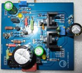
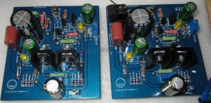
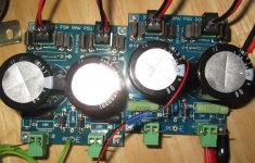
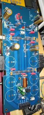
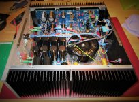
While waiting for the heatsinks I have been populating the OPS boards and the 1st IPS RCP130 SURYA EVO42.9964.
Here are some images...
Here are some images...
Attachments
To complete my offer of input stages, I wanted a high performance CFA.
Based on a design from Damir Verson, I am now working on a Lateral Mosfet output that promises spectacular distortion values.
The RCP130 DIASA EVO5.1 is now completed.
THD 1kHz @ 50W is 0.000085%
THD 20kHz @ 50W is 0.000167%
PM: 101° with GM 6dB (I am still working on the compensation as I find GM to be too low)
Included an offset null circuit used to minimize OPOFFSET before connecting the servo. This way the servo is not stressed and I can use a higher value for servo injection resistor.
Input filter optimized to avoid overshoot in the output.
To use the simulation in attach save the asc file and the txt file in the same directory, open the asc file in LTSPICE and place the following .op:
.include RCAUDIO MODELS 2021.txt
Attachments
The RCP130 is built.
The first IPS is the SURYA EVO42.994.... a cascoded jfet IPS biased by a ccs in the jfet source.
Offset due to termals is controlled by an optional servo.
The IPS jfet cascode is driven by the IPS signal by means of a level shifting transistor with the base connected to the jfets sources.
IPS Jfet is a dual LSK389 connected in parallel to reduce noise and increase gm. No source degeneration is used in this case.
How does it sound ?
The CFA architecture provides ultra wide bandwidth so ULGF is reached @ 1.4MHz. This correlates with the clean airy highs observed in all types of music.
Voice timbres are very good.
Bass is clean but can not compete with the slam factor I got from my best VFA built with a differential IPS.
Ear fine tuning is ongoing.
Attachments

How does it sound ?
The CFA architecture provides ultra wide bandwidth so ULGF is reached @ 1.4MHz. This correlates with the clean airy highs observed in all types of music.
Voice timbres are very good.
Bass is clean but can not compete with the slam factor I got from my best VFA built with a differential IPS.
Ear fine tuning is ongoing.
If you use the same OPS for IPS VFA or CFA I don't think that bass could sound differently, try to increase C30 to 2.2 uF.
Thank you Damir
I will try that and let you know.
BTW... Your design is magnificent and I never simulated an amp with such low THD.
What still worries me it is it's overshoot that can only be tamed by the input filter.
Square waves produce really nasty spikes in the base of Q6 (VAS).
I tried a lot of options but anything that I do increases THD.
I have one question... the 680p caps in the bases of the IPS cascodes Q33 Q34 are there to avoid cascode oscilations ?
Best
Thank you Damir
I will try that and let you know.
BTW... Your design is magnificent and I never simulated an amp with such low THD.
What still worries me it is it's overshoot that can only be tamed by the input filter.
Square waves produce really nasty spikes in the base of Q6 (VAS).
I tried a lot of options but anything that I do increases THD.
I have one question... the 680p caps in the bases of the IPS cascodes Q33 Q34 are there to avoid cascode oscilations ?
Best
I would not worry to match about square wave overshoot, it is normal two pole compensation behavior of very fast amp. If you like the music coming out of the amp, that is only important.
Yes, those caps are for better cascode behavior and also lower high frequency distortion somewhat.
BR
While discussing a new power amp with Hugh Dean, I understood the importance of the phase lead cap in the compensation of an lateral mosfet amplifier with drivers in the OPS.
In my singleton build (SURYA) I tried a simpler "pure miller" compensation and was not able to get rid of the slight overshoot that cause harshness in the treble.
Adding a small cap from the VAS collector to the NFB junction node did null the overshoot in simulation.
As this is a modular amp where I can easily remove the IPS, the mod was readily done.
The result confirms what I saw in simulation. Highs are now fast and clear without any sign of harshness.
Attachments
NOTE:
As the SURYA is a singleton IPS with current feedback, the clead cap does not work if placed parallel to the NFB series resistor (as it is normally done in the VFA models).
Why does it not work is to be investigated......
As the SURYA is a singleton IPS with current feedback, the clead cap does not work if placed parallel to the NFB series resistor (as it is normally done in the VFA models).
Why does it not work is to be investigated......
RCP130 M103C EVO48.42
The SURYA is now tuned and it sounds really good.
It is time for a new IPS.
I will call it the M130C as it is "heavily" based on the Meridian 103 from BS.
I always wanted to do this: Meridian 103 clone
Now that I am mastering LTSpice I am confident that this will work.
It is an inverting amplifier so input common mode distortion will be avoided.
Although the original amp relies on the two diodes D2 D4 to stabilize temp variations so offset is stable, I can try a servo-ed version as my OPS board already has the servo built in.
I did some math so now I fully understand how to determine FB values....
This arrangement is used to reduce the impedance of the NFB circuit.
Av is calculated like this:
Av = -R6(R5 + R4)/RiR4
Ri = R1+R2 11000
R5 4700
R4 400
R6 18000
Av 20.86 (26dB)
This amp does not need an input cap as the input node is at a virtual GND (Just like as in an inverting opamp configuration)
THD 20kHz @ 50W 8ohm is quite good:
Harmonic Frequency Fourier Normalized Phase Normalized
Number [Hz] Component Component [degree] Phase [deg]
1 2.000e+04 2.639e+01 1.000e+00 167.93° 0.00°
2 4.000e+04 1.823e-04 6.909e-06 17.86° -150.06°
3 6.000e+04 5.022e-04 1.903e-05 -79.31° -247.24°
4 8.000e+04 4.335e-05 1.643e-06 0.57° -167.35°
Total Harmonic Distortion: 0.002032%(0.002727%)
With actual compensation C4 15p Clead and shunt comp zobel R3 500ohm C1 680p I simulated 90.6° PM and 11.6dB GM
Below you can find the sch , layout and the asc file for amusement.
Attachments

- Home
- Amplifiers
- Solid State
- RCP130 modular lateral mosfet power amplifier