Having recently designed and built a modular power amplifier where the input stage can be easily exchanged while maintaining the PSU and output stage, I am now able to compare different IPS topologies.
After long listening tests I can now present a subjective comparison:
1 – SURYA Singleton IPS CFA topology
The CFA architecture provides wide bandwidth and this correlates with observed clean airy highs in all types of music. Voice timbres and wood stringed instruments are realistically presented.
The clean and tuneful Bass can realistically represent the lower registers but lacks the ultimate slam factor possible with a differential IPS.
2 – BRAHMA Differential IPS VFA topology
The LIN topology used with a Mirror loaded LTP IPS followed by a buffered TIS has a much higher OLG and the 1st pole is set very low compared with the Singleton approach.
Carefully chosen IPS degeneration allied with highly tuned TMC compensation, creates a machine able to convey a dramatic presentation exceling in bass control.
The differential IPS really reduces LF distortion so bass is tight and deep. The TMC helps because the reduced HF distortion provides the needed “cues” to render the bass snappy and very musical.
Treble is good but lacks the subtilty and realism of the singleton.
3 – MC103C Symmetrical inverting topology
The inverting power amplifier virtually eliminates common mode input distortion and in this symmetrical architecture I found a beautiful monotonic THD profile.
It seems that reducing input common mode distortion is the major player in the resulting sonic character.
In this case I noticed a very wide and deep soundstage with very well rendered treble.
Female voices, drum cymbals and metal wind instruments appear with high levels of realism.
Very low high frequency distortion and low noise permit the easy observation of microdetail. This topology permits a very musical high-definition amplifier with a velvety overall rendering.
4 - GAIA DIFPAIRVAS Differential VAS topology
Using a similar IPS as the one found in the BRAHMA but with a cascoded CCS in the LTP and a different driven cascode circuit, this design uses a differential TIS.
The cascoded CCS reduces common mode input distortion and the differential TIS assures a significant reduction of THD.
It sounds wide and deeper than the LIN with excellent bass control.
Voices are here presented with a realism on par with the singleton.
Effortless dynamics with detailed top end, this one is a top contender.
5 - KALI Folded Folded topology
Using a differential cascoded IPS followed by a folded cascode (AD826 style) this design provides wide bandwidth.
The cascoded CCS reduces common mode input distortion and the differential TIS assures a significant reduction of THD.
It sounds extremely detailed being able to separate the several instruments in a mix.
Voices are here presented realistically without any hint of male boom.
Excellent dynamics with even power delivery.
Bass is under control but not forward presented as in the LIN version.
Very low noise design helps with microdetail rendering.
6 - BIEL FCS Symmetrical topology
This one uses a Full Complementary symmetrical circuit Where the IPS is Mirror loaded.
Final solution (EVO8.33) can be found here: https://www.diyaudio.com/community/threads/slone-amp-final-solution.379346/
This amplifier is a top contender in it's final implementation.
Bass has a "Full On" characteristic being better detailed compared to all other builds.
Treble is open and clear and able to provide an "Airy" soundstage.
Instrument separation is excellent and voices are presented with very high realism.
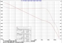
This amplifier has some spectacular simulation values:
111dB OLG until 600Hz
108dB @ 1KHz
59dB @ 20KHz
0dB @ 1.18MHz (66° PM and 22dB GM)
Damping factor into 8ohms is 5Mohm until 1KHz and 34Kohm @ 20KHz
My solution for the Slone amp (fixing VAS current only on the Top VAS bjt) might seem strange to some of you but it works very well, (VAS current is very stable and quite indifferent to Temp oscillations) and we do not loose on OLG as in some of the other solutions I have studied.
POST2: https://www.diyaudio.com/forums/sol...teral-mosfet-power-amplifier.html#post6557721 SURYA cascoded jfet singleton IPS and it's name is RCP130 SURYA
POST34 https://www.diyaudio.com/forums/sol...ral-mosfet-power-amplifier-2.html#post6686514 SURYA build first listening impressions
POST13: https://www.diyaudio.com/forums/sol...teral-mosfet-power-amplifier.html#post6619571 BRAHMA (Casoded Jfet LTP IPS)
POST29: https://www.diyaudio.com/forums/sol...ral-mosfet-power-amplifier-2.html#post6659035 Update on BRAHMA EVO44.2554
POST46: https://www.diyaudio.com/forums/sol...ral-mosfet-power-amplifier-3.html#post6726920 Final build of the RCP130 BRAHMA EVO44.255537.41 (Listening comparisons between the SURYA singleton and the BRAHMA Harry Lin topologies)
POST15: Third IPS ... RCP130 GAIA DIFPAIRVAS (Based on a design from Bob Cordell)
POST51 https://www.diyaudio.com/forums/sol...ral-mosfet-power-amplifier-3.html#post6763678 RCP130 GAIA DIFPAIRVAS build and subjective sonic evaluation
POST24: Fourth IPS ... RCP130 SHIVA Luxman (Hawksford cascoded sym VAS)
POST33: Fifth IPS ... RCP130 DIASA EVO5.1 (An incredibly low distortion CFA symmetrical IPS amplifier)
POST40 https://www.diyaudio.com/forums/sol...ral-mosfet-power-amplifier-2.html#post6696989 Sixth IPS ... RCP130 M103C EVO 48.42 Symetrical inverting amp with Tnetwork overall NFB
POST47 https://www.diyaudio.com/forums/sol...ral-mosfet-power-amplifier-3.html#post6733923 M103C EVO 48.42 Final build and listening impressions of the inverting amp
POST60 https://www.diyaudio.com/forums/sol...ral-mosfet-power-amplifier-3.html#post6768262 Seventh IPS, The Circle, is a CFA initially proposed by Miib
POST66 https://www.diyaudio.com/forums/sol...ral-mosfet-power-amplifier-4.html#post6819227 KALI FOLDED
After long listening tests I can now present a subjective comparison:
1 – SURYA Singleton IPS CFA topology
The CFA architecture provides wide bandwidth and this correlates with observed clean airy highs in all types of music. Voice timbres and wood stringed instruments are realistically presented.
The clean and tuneful Bass can realistically represent the lower registers but lacks the ultimate slam factor possible with a differential IPS.
2 – BRAHMA Differential IPS VFA topology
The LIN topology used with a Mirror loaded LTP IPS followed by a buffered TIS has a much higher OLG and the 1st pole is set very low compared with the Singleton approach.
Carefully chosen IPS degeneration allied with highly tuned TMC compensation, creates a machine able to convey a dramatic presentation exceling in bass control.
The differential IPS really reduces LF distortion so bass is tight and deep. The TMC helps because the reduced HF distortion provides the needed “cues” to render the bass snappy and very musical.
Treble is good but lacks the subtilty and realism of the singleton.
3 – MC103C Symmetrical inverting topology
The inverting power amplifier virtually eliminates common mode input distortion and in this symmetrical architecture I found a beautiful monotonic THD profile.
It seems that reducing input common mode distortion is the major player in the resulting sonic character.
In this case I noticed a very wide and deep soundstage with very well rendered treble.
Female voices, drum cymbals and metal wind instruments appear with high levels of realism.
Very low high frequency distortion and low noise permit the easy observation of microdetail. This topology permits a very musical high-definition amplifier with a velvety overall rendering.
4 - GAIA DIFPAIRVAS Differential VAS topology
Using a similar IPS as the one found in the BRAHMA but with a cascoded CCS in the LTP and a different driven cascode circuit, this design uses a differential TIS.
The cascoded CCS reduces common mode input distortion and the differential TIS assures a significant reduction of THD.
It sounds wide and deeper than the LIN with excellent bass control.
Voices are here presented with a realism on par with the singleton.
Effortless dynamics with detailed top end, this one is a top contender.
5 - KALI Folded Folded topology
Using a differential cascoded IPS followed by a folded cascode (AD826 style) this design provides wide bandwidth.
The cascoded CCS reduces common mode input distortion and the differential TIS assures a significant reduction of THD.
It sounds extremely detailed being able to separate the several instruments in a mix.
Voices are here presented realistically without any hint of male boom.
Excellent dynamics with even power delivery.
Bass is under control but not forward presented as in the LIN version.
Very low noise design helps with microdetail rendering.
6 - BIEL FCS Symmetrical topology
This one uses a Full Complementary symmetrical circuit Where the IPS is Mirror loaded.
Final solution (EVO8.33) can be found here: https://www.diyaudio.com/community/threads/slone-amp-final-solution.379346/
This amplifier is a top contender in it's final implementation.
Bass has a "Full On" characteristic being better detailed compared to all other builds.
Treble is open and clear and able to provide an "Airy" soundstage.
Instrument separation is excellent and voices are presented with very high realism.
This amplifier has some spectacular simulation values:
111dB OLG until 600Hz
108dB @ 1KHz
59dB @ 20KHz
0dB @ 1.18MHz (66° PM and 22dB GM)
Damping factor into 8ohms is 5Mohm until 1KHz and 34Kohm @ 20KHz
My solution for the Slone amp (fixing VAS current only on the Top VAS bjt) might seem strange to some of you but it works very well, (VAS current is very stable and quite indifferent to Temp oscillations) and we do not loose on OLG as in some of the other solutions I have studied.
POST2: https://www.diyaudio.com/forums/sol...teral-mosfet-power-amplifier.html#post6557721 SURYA cascoded jfet singleton IPS and it's name is RCP130 SURYA
POST34 https://www.diyaudio.com/forums/sol...ral-mosfet-power-amplifier-2.html#post6686514 SURYA build first listening impressions
POST13: https://www.diyaudio.com/forums/sol...teral-mosfet-power-amplifier.html#post6619571 BRAHMA (Casoded Jfet LTP IPS)
POST29: https://www.diyaudio.com/forums/sol...ral-mosfet-power-amplifier-2.html#post6659035 Update on BRAHMA EVO44.2554
POST46: https://www.diyaudio.com/forums/sol...ral-mosfet-power-amplifier-3.html#post6726920 Final build of the RCP130 BRAHMA EVO44.255537.41 (Listening comparisons between the SURYA singleton and the BRAHMA Harry Lin topologies)
POST15: Third IPS ... RCP130 GAIA DIFPAIRVAS (Based on a design from Bob Cordell)
POST51 https://www.diyaudio.com/forums/sol...ral-mosfet-power-amplifier-3.html#post6763678 RCP130 GAIA DIFPAIRVAS build and subjective sonic evaluation
POST24: Fourth IPS ... RCP130 SHIVA Luxman (Hawksford cascoded sym VAS)
POST33: Fifth IPS ... RCP130 DIASA EVO5.1 (An incredibly low distortion CFA symmetrical IPS amplifier)
POST40 https://www.diyaudio.com/forums/sol...ral-mosfet-power-amplifier-2.html#post6696989 Sixth IPS ... RCP130 M103C EVO 48.42 Symetrical inverting amp with Tnetwork overall NFB
POST47 https://www.diyaudio.com/forums/sol...ral-mosfet-power-amplifier-3.html#post6733923 M103C EVO 48.42 Final build and listening impressions of the inverting amp
POST60 https://www.diyaudio.com/forums/sol...ral-mosfet-power-amplifier-3.html#post6768262 Seventh IPS, The Circle, is a CFA initially proposed by Miib
POST66 https://www.diyaudio.com/forums/sol...ral-mosfet-power-amplifier-4.html#post6819227 KALI FOLDED
Attachments
Last edited:
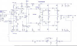
RCP130 IPS circuit description:
R6 - 1kohm
C4 - 220pF
R5 - 50kohm
Form the input filter and load
Q5 Q8 is a dual JFET LSK389B parallel connected (to lower noise and increase gm) without source degeneration resistors.
R7 and R11 - 100ohms are placed between the LSK drains and the cascode device Q6 as these help to maintain constant power dissipation in the jfets.
R3 - 330ohm is the IPS load
Q6 - KSC1845 is the cascode device and it's base is biased by a hawksford / dadod method comprised by R49 - 47k, R10 - 15k, Q3 - KSA992.
With this arrangement, the cascode bias is modulated by the signal present in the sources of the input devices but the cascode bias current is not injected directly in the sources of the input jfets.
Q4 - KSC3503 together with R13 - 20kohm, R27 - 100ohms, C3 - 100uF, D5 - RED LED, R28 - 330ohms and R45 - 1ktrimmer, form the input stage biasing CCS responsible by managing the output offset.
R21 - 1k2ohm
R25 - 56ohm
C5 - 4700uF // 100n
Form the feedback voltage divider.
Q2 - KSA992 is the VAS Beta enhancer and Q18 is the VAS
Q11 - KSC3503 along with R48 - 20komh, R4 - 100ohm, R8 - 100ohm, C33 - 100uF and D1 - RED LED form the VAS CCS load.
C12 is the miller capacitor
As this design uses Laterals for the output, I do not need an active VBE "spreader" and I am using R17 - 750ohms in parallel with a 2ktrimmer to produce the voltage spreading needed for biasing the OPS.
Although the ccs under the IPS is used to set and minimize the output offset, it takes a long time to settle (due to temperature variations) so I implemented a DC servo using a jfet input opamp LF411 powered by a dedicated PSU based on TL431 references.
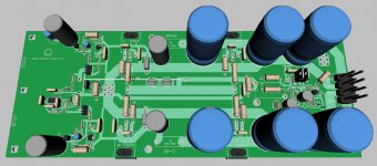
The output stage is very simple with two pairs of Laterals.
For the drivers I chose the plastic KSC3503 / 1381.
D6 D13 D11 D15 limit the voltage spread in the laterals gates so in case of input overdrive, the Vgs of the outputs never go higher than 12V.
The output stage is very simple with two pairs of Laterals.
For the drivers I chose the plastic KSC3503 / 1381.
D6 D13 D11 D15 limit the voltage spread in the laterals gates so in case of input overdrive, the Vgs of the outputs never go higher than 12V.
Have you seen Bob Cordell’s use of 220k resistors and 1N4149 diodes to bias the clamping diodes ?
Between,you, Nelson , and Bob my life has more projects than minutes, at least you all use the same devices for drivers so I can justify buying 100 of each................
Between,you, Nelson , and Bob my life has more projects than minutes, at least you all use the same devices for drivers so I can justify buying 100 of each................
Last edited:
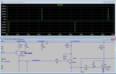
While simulating the effect of the DC servo I found a nasty looking spice in the OLG near 5Hz.
This was when I connected the IPS cascode bias Hawksford style injecting it's current directly in the IPS sources....
After reading and studying the subject and following this idea: https://www.diyaudio.com/forums/solid-state/248105-slewmaster-cfa-vs-vfa-rumble-3.html#post3766356
I implemented Dadod's connection that almost made the spike disappear.
Attachments
Last edited:
Also during simulations with square waves I found the signal to be distorted in the base of the VAS while using C35 C36 over the Drivers.
I will leave space in the PCB for those but maybe I can get away just by using the typical base stoppers R19 and R20
I will leave space in the PCB for those but maybe I can get away just by using the typical base stoppers R19 and R20
Attachments
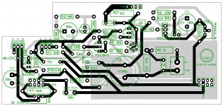
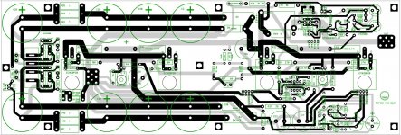
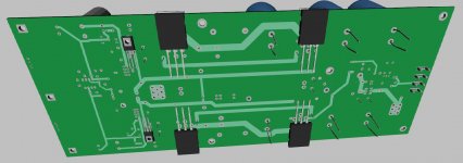
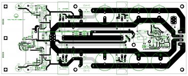
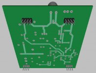
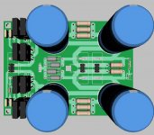
After serious consideration I changed the OPS layout that is now more compact and does not include the rectifying diodes.
Attachments
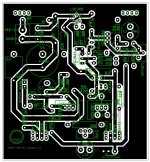
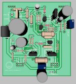
The IPS corresponding to the singleton cascoded jfet was also modified to mate the OPS board.
Attachments
While waiting for the boards, here we have the next IPS...
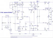
The RCP130 LAKSHMI is the natural evolution of my P300.
In this case we have a cascoded Jfet LTP.
The cascode is referenced to the IPS sources using a buffer (special arrangement provided by DADOD)
The buffered VAS has a third transistor used as an active clamp (special arrangement borrowed from OS designs)
The TMC compensation is similar to the one used in the P300.
Attachments
Now it is time for the third IPS design.
I read about the SymAsym5_3 and did some simulations... the compensation is quite complex and although I was able to reach a good THD, some cap values are critical to the stability and distortion so I went back to Bob Cordell Book and found this wonder.
I call it the RCP130 Cordell Diffpairvas.
After some simplifications and modifications on the compensation scheme I reached worldclass simulations.
With a 20khz signal @ 50W into 8ohm:
Harmonic Frequency Fourier Normalized Phase Normalized
Number [Hz] Component Component [degree] Phase [deg]
1 2.000e+04 2.823e+01 1.000e+00 -4.01° 0.00°
2 4.000e+04 2.775e-04 9.830e-06 69.60° 73.61°
3 6.000e+04 1.486e-04 5.264e-06 151.42° 155.42°
4 8.000e+04 5.159e-05 1.827e-06 38.91° 42.92°
Total Harmonic Distortion: 0.001130%(0.003554%)
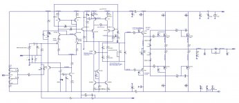
Relative to the SymAsym the major difference lies on the Diff VAS that now is buffered with two source followers Q12 Q13.
The current in the VAS emitters is now provided by a double CCS Q16 Q17.
The VAS Mirror is "helped" by a third transistor Q15 that needs a cap for stabilization C13 470p.
The IPS is designed around cascoded jfets and I included diodes D17 D18 that avoid saturation of Q10 Q11, providing a soft clipping.
To reach worldclass 20khz THD I am using TMC compensation C6 C14 R51.
C3 over the series FB resistor is there to increase stability.
I will design the PCB layout and build it so I can confirm the compensation scheme.
Attachments
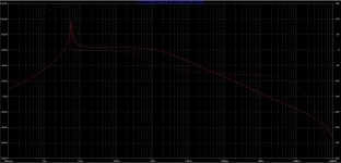
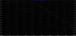
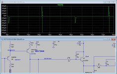
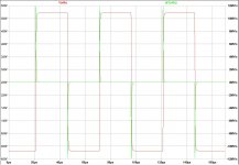
Squares are nicely handled and I did not find any misbehaving anywhere.
Here we see the response in the NFB node:
PS: The SR measurements where made with the IPS filter in place.... the actual value is doubled without the filter.
Here we see the response in the NFB node:
PS: The SR measurements where made with the IPS filter in place.... the actual value is doubled without the filter.
Attachments
Note that to increase gm and lower noise I decided to up the tail current of the IPS to 8mA.
The dissipation in the IPS current source can be high so I am using a mid power transistor there. The 2SC3503 has rather high VA (Early Voltage) so it is a very good candidate for this CCS.
The dissipation in the IPS current source can be high so I am using a mid power transistor there. The 2SC3503 has rather high VA (Early Voltage) so it is a very good candidate for this CCS.
- Home
- Amplifiers
- Solid State
- RCP130 modular lateral mosfet power amplifier