Thank you Damir
I will try that and let you know.
BTW... Your design is magnificent and I never simulated an amp with such low THD.
What still worries me it is it's overshoot that can only be tamed by the input filter.
Square waves produce really nasty spikes in the base of Q6 (VAS).
I tried a lot of options but anything that I do increases THD.
I have one question... the 680p caps in the bases of the IPS cascodes Q33 Q34 are there to avoid cascode oscilations ?
Best
Hi Ricardo,
Have you tried with higher value input cap?
BR Damir
Hi Damir
I am still working on the pcb layout for your amp.
I will let you know when I get it working.
Note: Hope it sounds as good as the Gainwire I built with your boards 🙂
Meanwhile I would really appreciate your comment regarding my attempt to build a Meridian 103 Clone.
I did a good simulation but need some input regarding the topology because I am not familiar with.
Please go to: https://www.diyaudio.com/forums/sol...ral-mosfet-power-amplifier-2.html#post6696989
In your opinion what is the purpose of the two transistors Q5 and Q6 ?
I am not familiar with this amp, I have to simulate it too, but I don't have transistor models you are using, I will gibe it try with the models I have.
The BRAHMA input stage is up and running.
It is a LIN topology that uses a cascoded jfet IPS.
The cascode bjt bases are driven by the output signal via a FB circuit with values identical to the main NFB circuit. (R29 R30 constitute a replica of the NFB network R58 R62)
This way input common mode distortion is reduced by reducing the variations in voltage between input jfet drain to gate.
The IPS mirror uses an helper transistor (EFA) so the voltage difference between the mirror collectors (Q13 Q14) is minimized enabling the use of a clamping diode D2 that avoids saturation of the mirror bjts providing a cleaner clipping.
The VAS (Q9) is buffered by a common emitter (Q16) and the TMC is set around this arrangement.
VAS current is set to 9.3mA as this way I can use rather high values for miller compensation without "muffling" the high freq response.
The notable HF distortion reduction provided by the TMC allied to the low distortion possible with the diff IPS produces a totally different sonic rendition (relative to the SURYA singleton IPS already presented in this thread).
The singleton IPS of the SURYA produces very clear and organic mid/high frequency response but the 2nd harmonic is ever present so the bass is not so tight.
The diff IPS of the BRAHMA really reduces LF distortion so bass is tight and deep. The TMC helps because the reduced HF distortion provides the needed "cues" to render the bass snappy and very musical.
I am pleased to notice the although the singleton is the most silent amp I built so far, the diff IPS biased @ 8mA also provides a very silent power amp.
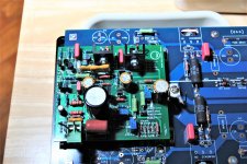
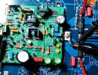
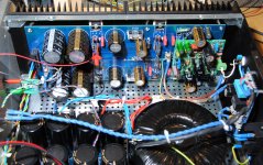
Some pictures are presented below where the test OPS board is shown:
It is a LIN topology that uses a cascoded jfet IPS.
The cascode bjt bases are driven by the output signal via a FB circuit with values identical to the main NFB circuit. (R29 R30 constitute a replica of the NFB network R58 R62)
This way input common mode distortion is reduced by reducing the variations in voltage between input jfet drain to gate.
The IPS mirror uses an helper transistor (EFA) so the voltage difference between the mirror collectors (Q13 Q14) is minimized enabling the use of a clamping diode D2 that avoids saturation of the mirror bjts providing a cleaner clipping.
The VAS (Q9) is buffered by a common emitter (Q16) and the TMC is set around this arrangement.
VAS current is set to 9.3mA as this way I can use rather high values for miller compensation without "muffling" the high freq response.
The notable HF distortion reduction provided by the TMC allied to the low distortion possible with the diff IPS produces a totally different sonic rendition (relative to the SURYA singleton IPS already presented in this thread).
The singleton IPS of the SURYA produces very clear and organic mid/high frequency response but the 2nd harmonic is ever present so the bass is not so tight.
The diff IPS of the BRAHMA really reduces LF distortion so bass is tight and deep. The TMC helps because the reduced HF distortion provides the needed "cues" to render the bass snappy and very musical.
I am pleased to notice the although the singleton is the most silent amp I built so far, the diff IPS biased @ 8mA also provides a very silent power amp.
Some pictures are presented below where the test OPS board is shown:
Attachments

RCP130 M103C EVO48.422 final build
As promised (to myself at least) I built a symmetrical inverting amp heavily based on the M103 that I consider one of the best sounding amps commercially available.
The RCP130 M103C EVO48.422 is an inverting amp with global NFB implemented with a T network in order to lower the NFB noise.
This type of configuration also avoids common mode input distortion.
Although offset can be trimmed it does fluctuate a little with temp rise so I added a servo. (Due to the atypical gnd arrangement on my proto board, if differential offset is greater than 10mv, and the preamp shares the same gnd for both channels, we can hear hum.... the servo cures that)
Sonic attributes:
I am glad to report that the original "air" ,wide and deep soundstage and very well rendered treble is also apparent in this implementation.
Voices are rendered with high levels of realism and drum cymbals are a pleasure to listen to.
I was hoping to get better bass detail (compared to the original) but although it is much stronger it just represents an enlarged version of the original without increase in detail.
So regarding bass rendition I would place this amp between the BRAHMA (LIN) and the SURYA (Singleton).
It is a very musical high definition amplifier with a velvety overall presentation. Not better, just different from the low noise kings)
Attachments

Interesting to notice that this design is unstable if the input GND is lifted (normally I do that with a 10ohm resistor between the input GND and power GND).
So it is somehow more susceptible to input GND hum issues.
I wanted to have 10mA in the VAS so I increased the current in the IPS from 300uA to 420uA.... this and the high IPS emitter resistors (R7 R11 470ohms) contribute to a higher noise in the output of the amp.
So it is somehow more susceptible to input GND hum issues.
I wanted to have 10mA in the VAS so I increased the current in the IPS from 300uA to 420uA.... this and the high IPS emitter resistors (R7 R11 470ohms) contribute to a higher noise in the output of the amp.
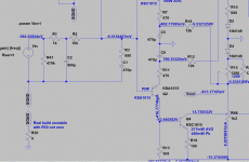
RCP130 GAIA DIFPAIRVAS
RCP130 GAIA DIFPAIRVAS
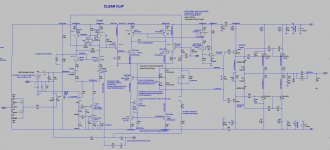
A new differential TIS, ultra-low distortion clean clipping power amplifier.
Now I know that I need a mirror loaded differential IPS to have enough OLG so to increase LF control.
I also need very low noise in the IPS so microdetail is easily apparent.
I also believe that minimal common mode distortion is fundamental to obtain a deep soundstage.
Inverting amplifiers need a complex NFB circuit designed to minimize it's impedance and the IPS can not be gnd lifted as the input is a virtual gnd.
So while reading Bob Cordell's second edition book I found a very interesting approach depicted in Fig 9.15 page 209.
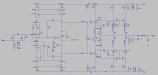
Here I am presenting my take on the differential pair VAS with mirror load:
RCP130 GAIA DIFPAIRVAS
A new differential TIS, ultra-low distortion clean clipping power amplifier.
Now I know that I need a mirror loaded differential IPS to have enough OLG so to increase LF control.
I also need very low noise in the IPS so microdetail is easily apparent.
I also believe that minimal common mode distortion is fundamental to obtain a deep soundstage.
Inverting amplifiers need a complex NFB circuit designed to minimize it's impedance and the IPS can not be gnd lifted as the input is a virtual gnd.
So while reading Bob Cordell's second edition book I found a very interesting approach depicted in Fig 9.15 page 209.
Here I am presenting my take on the differential pair VAS with mirror load:
Attachments
Last edited:
This new RCP130 GAIA version minimizes common mode input distortion (CMID), has very low noise and clips cleanly.
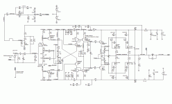
Circuit description for the EVO10.822C
LTP IPS:
Dual LSK389B NJfet is judiciously degenerated by R3 and R4. This enables me to use high standing current to increase Slew rate while reducing input noise.
The LTP current is set by a cascoded CCS that reduces CMID. The current is limited to 6.6mA to reduce power dissipation. Each base of the ccs bjts are filtered with an RC 100ohm/220u, increasing its PSRR and increasing output impedance of the ccs.
As CMID can be introduced at HF by the non-linear collector/gate capacitance of the jfets, these are cascoded by Q21 and Q20.
In order to reduce thermal memory distortion, we need to enforce a constant junction temperature in the jfets that will now maintain a constant power dissipation. This is achieved by modulating the cascode base bias current with a replica of the LTP tail signal and so creating a driven cascode. This is done by buffering the LTP signal with Q9 and feeding the result into the cascode bias arrangement R13 / R60.
D17 and D18 (1N4149 low capacitance diodes) clamp the IPS so the mirror transistors Q10 and Q11 are not saturated during clipping.
The mirror Q10 Q11 uses a “helper” transistor Q14 to improve it’s operation. The 470p capacitor C15 helps to stabilize this arrangement.
VAS LTP:
The PNP VAS LTP Q4/Q5 are preceded by NPN emitter followers Q12/Q13 so Vbe drops are canceled and these buffers present a much lower load to the IPS.
The VAS is fed from both outputs of the IPS LTP.
VAS LTP is powered by a twin CCS Q24/Q17/Q16/Q23/Q25. This dual CCS arrangement preserves voltage headroom because no current flows through the VAS emitter degeneration resistor R16 that sets VAS gain.
In order to increase this ccs output impedance, diode D16 was included in Q15 emitter. This diode effectively increases the reference voltage around the current setting resistor R59. For the same CCS current we can now use a higher value resistor as R59 and that increases CCS output impedance.
The LTP VAS is mirror loaded by Q7/Q8/Q15. (Q15 is the “helper” and it’s stability ensured by C13 470p)
The cascode Q6 is included between Q4 and the lower mirror. It lowers collector voltage of Q4 reducing voltage difference between colectors of Q4/Q5 so the pair remains thermally balanced.
Power amplifier compensation:
C6/C14/R51 form the TMC arrangement that is responsible by low HF THD.
C6 100p is the typical miller capacitor. C14 470p in series with C6 reduces it,s value to the nominal 82p needed for stability.
R51 1k8ohms connected to the output, bootstraps C14 so it does not effectively load VAS output.
C10 / C12 connected between VAS output and GND force phase to be constant from 1khz to 20khz while reducing THD @ 20khz.
R17 / R18 used to connect VAS output to gnd reference. It’s high value (2Meg ohm) do not load the VAS and do not affect THD. These resistors simply avoid leaving the VAS output floating and so it reduces this node sensivity to parasitic capacitances that might be found in the PCB.
Offset control:
Voltage divider R19/D12 13 14 15/R20 and 10k pot (R15-R14) determine the voltage to be applied through the injection resistor R42 into the NFB circuit.
NFB circuit:
R46 (15kohm) and R12 (680ohm) form the NFB voltage divider that sets the gain of the amplifier.
The reduced values of R46/R12 lower considerably the amp noise.
C5 (2200uF) // C7(2u2) are used to reduce gain to unity at DC so offset is minimized.
@ Bob Cordell
Hi Bob
First of all I must congratulate your work on your Book.
I hope you do not mind me building an amp based on your model page 209.
It is a major improvement over the LIN topology I built before.
I would appreciate your comments on my implementation.
In your example you chose a low tail current for the LTP IPS and quite large source degeneration.
In my case I am using a much higher current (6.6mA) and lower emitter resistors (100ohm).
Why did you chose such low current value ?
Best
Ricardo
You might want to look at changing the temperature or voltage and seeing how it reacts. I've noted in some designs that variations from ideal conditions can impact performance significantly.
I haven't scrutinized the circuit, so can't say if this design could be sensitive to this.
I haven't scrutinized the circuit, so can't say if this design could be sensitive to this.
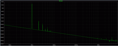
Here you have a LTSPICE sim (Transient) where I included the models I am using so it is easier to run.
The step param SWV is used to run the sim twice so we can view the results and FFT with and without load. (Without load the output stage distortion is not apparent so we can see the distortion of the IPS and VAS only).
The step param SWV is used to run the sim twice so we can view the results and FFT with and without load. (Without load the output stage distortion is not apparent so we can see the distortion of the IPS and VAS only).
Attachments
Hi BrianYou might want to look at changing the temperature or voltage and seeing how it reacts. I've noted in some designs that variations from ideal conditions can impact performance significantly.
I haven't scrutinized the circuit, so can't say if this design could be sensitive to this.
Thank you for your comment.
Please see my previous post where you can use the command .STEP TEMP LIST 25 75.
To speed things up a bit you should disable .step param SWV list 0 1 and enable ;param SWV 1
To change the load use .param rload=8
To change output power use .param power=50
To change frequency use .param freq 20k
To change rail voltages use .param vsup=57
Do not change .param gain=15k/680 as you would get wrong measurements everywhere
Spice error log shows some results from the MEAS commands
To change Spice error THD precision, use 0.1 for 1khz in .param delay 0 and 0.01 for 20khz
PS: All these commands are already included in my sim....
Last edited:
To speed up simulations I start with delay 0
But in this case, to correctly view FFT results I must select Specify a time range and use 0.1ms for 20khz sim and 2ms for 1khz...
But in this case, the error log results are not very accurate.
But in this case, to correctly view FFT results I must select Specify a time range and use 0.1ms for 20khz sim and 2ms for 1khz...
But in this case, the error log results are not very accurate.
If you want to view the results for unloaded only, disable .step param SWV list 0 1
and set ;param SWV 1 to 0
and set ;param SWV 1 to 0
RCP GAIA DIFPAIRVAS Sound
I can finally post some subjective listening impressions.
Bass is very detailed and articulated, able to faithfully reproduce the lower registers without blurring.
It goes very low and I consider it on par with the results obtained with the LIN topology amp.
Mids are better here than with the LIN... Not so dramatic, with more microdetail so I can hear better differentiation between instruments.
Voices are presented in a very realistic way without any hint of sibilance.
Treble is markedly better than with the LIN. It is extended and fluid without nasties.
It is better than the singleton because it retains the organic voice rendition with very extended and fluid treble but with much better bass.
It does not surpass the inverting amp MC103C in the size and depth of image but is very near, being also able to produce an engaging sound field with credible piano and voices.
Attachments

RCP130 THE CIRCLE
Back to the singleton idea, I am now studying a new CFA.
This time I am using this idea coming from Miib: https://www.diyaudio.com/forums/solid-state/258549-assemblage-power-amp-21.html#post4094741
The original design is meant to power the output laterals directly but as my modular power amp has drivers, I adapted the schematic and added a servo.
I have some doubts regarding the filter on the servo output and so opened this: https://www.diyaudio.com/forums/solid-state/376355-dc-servo-rc-filter-question.html#post6768160
Hope someone is interested.....
Attachments
- Home
- Amplifiers
- Solid State
- RCP130 modular lateral mosfet power amplifier