Explain which filter will help reduce the noise and distortion of this amplifier by 30 ... 40 dB in this test.
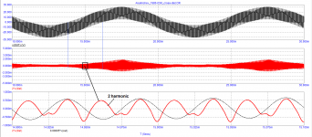
There are two frequencies at the input, clean, without additional harmonics
Why, in steady-state mode, the distortions of two amplifiers on a sinusoidal signal are the same, and the IMD test shows a difference of 30 ... 40 dB
Start a different thread for a new discussion. I'm not interested.
Jan
Now let's turn to a simple development of Russian radio amateurs. The voltage amplifier was proposed by Maxim Vasiliev, and the output stage was developed by Dmitry Kireev.
The features of the output stage include the fact that it is capable of working from peak to peak (Rail-to-Rail), the bias circuit for maintaining the quiescent current (bias) has an isolated power supply with a voltage of 5 V.
The signal propagation delay time is 60 ns, the duration of the linear section is more than 1 MHz, at the end there is a smooth fall. With a smooth decline, the time to reach the steady state does not exceed 2 * tPD. In this case, this time is no more than 100 ... 150 ns, which guarantees negligible speed distortions.
Ah, this scheme. For my favorite, I abandoned the parallel amplifier and preferred the usual complementary output stage on inexpensive, affordable bipolar transistors.
Sincerely, M. Vasiliev
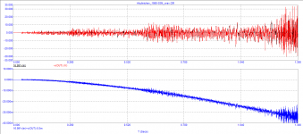
let's give a sound signal to the amplifier input
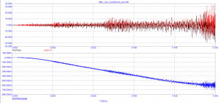
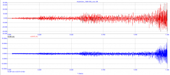
As we can see, by the end of the first second, a constant voltage of more than 0.5 V appeared at the output. Moreover, the voltage amplifier is to blame for this, the output stage is not to blame. By the end of the test signal, the peak-to-peak vector error amplitude reached almost 200 mV.
As we can see, by the end of the first second, a constant voltage of more than 0.5 V appeared at the output. Moreover, the voltage amplifier is to blame for this, the output stage is not to blame. By the end of the test signal, the peak-to-peak vector error amplitude reached almost 200 mV.
Attachments
The only thing I have learned so far is that wideband noise is supposed to increase when performing an IMD test.
Could this be an artefact of the test setup?
But let’s assume it is true, then the implication is that while playing music the same effect will happen.
But since in the images shown it concerns harmless white noise, I don’t see the problem because the noise will be way below music level.
The discussion reminds me of an experiment in another thread where I prepared three wav files from a 192k/24 master downsampled to 44.1/24 and 44.1/16 and then upsampled again to 192/24 masked with noise above 44.1 and below 16 bits.
Those who claimed to hear big differences between 192k/24 and 44.1k/16 where unable to select the original version.
So to conclude, the GD theory affecting sound reproduction should be tested in a proper way, not with an oscilloscope but with humans.
It would be easy to use a WB amp with a switch to increase GD.
Who knows, it could bring something, but since this theory was already presented some 40 years ago, I find it difficult to believe that it was completely overlooked by all those manufacturers desperately seeking for how to standing out from the crowd.
Hans
Petr,
As an example, my amp produces 14uV@20Khz BW.
With 1Watt in 8R load, s/n is 106dB.
Suppose the noise increases by 20dB while playing, then s/n is still 86dB, a perfect result, far beyond your ability to hear any noise.
With higher volumes s/n becomes even better.
So I think your “noise bias” theory needs some revision.
Hans
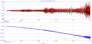
We have to repeatedly hear complaints about the work of amplifiers with servo control. I checked the voltage at the output of the operational amplifier responsible for the servo control, it is only 140 mV. Disconnected the servo control, balanced the amplifier and ran the test again
Attachments
He is predictable, again and again and........................
Well, when the boulder rolls down the hill you have to push it back up again.
We have to repeatedly hear complaints about the work of amplifiers with servo control. I checked the voltage at the output of the operational amplifier responsible for the servo control, it is only 140 mV. Disconnected the servo control, balanced the amplifier and ran the test again
We also repeatedly hear complaints about copper wire and cables on the floor. Do you also believe those?
And the device included in the signal circuit a servo drive (integrator)?) does not on affect the loop gain of the power amplifier? In the low-frequency domain ? And doesn't introduce a pretty decent level of distortion ?Мы также неоднократно слышим жалобы на медную проволоку и кабели на полу. Вы тоже в это верите?
Last edited:
@ Hans Polak: Well Hans, you probably get it by now. Every time you reply to something, the subject is changed.
Hope you enjoy that ;-)
Jan
Hope you enjoy that ;-)
Jan
Hi Jan,
I enjoy the BS theories with the “first and last cycle distortion” from a filter.
Just as the impulse response from a CD showing even more severe pre- as wel as post ringing when using FIR filters.
Is that distortion ? In a pure graphical way yes, but we do not regard that as distortion.
Just a matter of removed HF content from the signal.
It is a convolution between filter and signal resulting in a new signal with a modified shape. No distortion or whatsoever is basically involved by this operation.
Hans
No it's obviously not distortion but gurus make up their own definitions, like this one for noise.... https://www.diyaudio.com/forums/full-range/365242-softly-coupling-driver-cabinet-4.html#post6469871
That's right, because the integrator is connected to the summation point and there is an influence.If the correction signal is mixed with the error signal of the OOS at the junction point of the resistors of the oos circuit, the influence of the integrator will decrease.Turning off the servo control system in the second amplifier and balancing it also removes the DC component at the amplifier output
Petr,
An integrator does nothing else but trying to bring the average of the received signal to zero volt.
So either the input signal is not symmetrical around zero volt or the integrator is connected to a wrong position, so don't blame the integrator, it's doing what's asked for.
The other thing, when you are not happy with the lead in and lead out of a signal, no matter whether this has any influence on the sound, you can improve things.
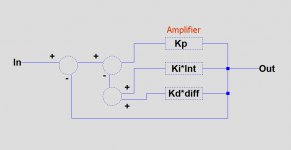
Regard the Amp as a Proportional controlled system.
When adding an Integrator to bring the DC component to zero, you have a PI system.
You can even go one step further and turn it into a PID system by adding a differentiator.
this can be a simple opamp, just like the integrator, but now with an RC network at it's input and some gain setting resistors around the opamp to get the required gain Kd.
That could be bring some interesting results.
Hans
.
An integrator does nothing else but trying to bring the average of the received signal to zero volt.
So either the input signal is not symmetrical around zero volt or the integrator is connected to a wrong position, so don't blame the integrator, it's doing what's asked for.
The other thing, when you are not happy with the lead in and lead out of a signal, no matter whether this has any influence on the sound, you can improve things.
Regard the Amp as a Proportional controlled system.
When adding an Integrator to bring the DC component to zero, you have a PI system.
You can even go one step further and turn it into a PID system by adding a differentiator.
this can be a simple opamp, just like the integrator, but now with an RC network at it's input and some gain setting resistors around the opamp to get the required gain Kd.
That could be bring some interesting results.
Hans
.
Attachments
That's what's exciting about the integrator.Its effect on the loop gain from the general oos chain. or is this a contrived problem?


“Gold-ear” listeners claim that the appearance of a constant component during the operation of the servo control system of more than 30 ... 40 mV is already noticeable in the sound.
However, let's not deviate from the topic: "the influence of the time Propagation Delay on the accuracy of amplification of audio signals"
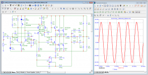
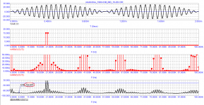
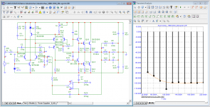
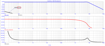
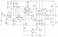
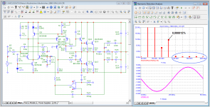
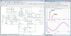
Baxandall made a great contribution on this topic. Among Russian radio amateurs, I. Akulinichev continued his work. He also used a vector meter to measure distortion. Here is one of his developments with a slight modification to increase the output power.
The quiescent current of the output transistors (bias) is 125 mA, the signal propagation delay time is not more than 50 ns and is stable up to a frequency of 4 MHz. Due to this, at a frequency of 200 kHz, there is no gain roll-off, the output signal practically merges with the input signal multiplied by Ku. The distortion spectrum is short, falling, the 2nd harmonic prevails in the spectrum. Class AB amplifier, but no switching distortion. The servo control signal level at 20 Hz is less than 90 dB (norm is less than 40 dB) than the input signal level.
The rest of the parameters are reflected in the test results and are presented in the figures.
However, let's not deviate from the topic: "the influence of the time Propagation Delay on the accuracy of amplification of audio signals"
Baxandall made a great contribution on this topic. Among Russian radio amateurs, I. Akulinichev continued his work. He also used a vector meter to measure distortion. Here is one of his developments with a slight modification to increase the output power.
The quiescent current of the output transistors (bias) is 125 mA, the signal propagation delay time is not more than 50 ns and is stable up to a frequency of 4 MHz. Due to this, at a frequency of 200 kHz, there is no gain roll-off, the output signal practically merges with the input signal multiplied by Ku. The distortion spectrum is short, falling, the 2nd harmonic prevails in the spectrum. Class AB amplifier, but no switching distortion. The servo control signal level at 20 Hz is less than 90 dB (norm is less than 40 dB) than the input signal level.
The rest of the parameters are reflected in the test results and are presented in the figures.
Attachments
-
 07_Akulinichev_1980-03M_cros-distortion.png28.6 KB · Views: 123
 -
 08_Akulinichev_1980-03M_200kHz.png78.5 KB · Views: 136
 -
 09_Akulinichev_1980-03M_no-servo_wav_vector-error.png28.3 KB · Views: 131
 -
 10_Akulinichev_1980-03M_wav_vector-error.png29.1 KB · Views: 98
 -
 06_Akulinichev_1980-03M_IMD_19-20kHz.png31.2 KB · Views: 109
 -
 05_Akulinichev_1980-03M_THD-vs-Freq.png108.9 KB · Views: 135
 -
 04_Akulinichev_1980-03M_20kHz-spectr_(FCD).png78 KB · Views: 161
 -
 03_Akulinichev_1980-03M_20kHz-spectr.png80.6 KB · Views: 164
 -
 02_Akulinichev_1980-03M_Bode.png23 KB · Views: 200
 -
 01_Akulinichev_1980-03M_SCH.png29.3 KB · Views: 194
Many have acoustics with high sensitivity and the quality of the first Watt is important for them. At low power, the distortions of the amplifier I. Akulinichev are negligible, the spectrum is short, which cannot be said about a more complex amplifier
Attachments
Petr,
You might have thought that I was kidding when mentioning the option for a PID control system.
Well, I was not.
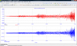
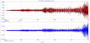
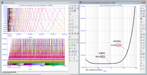
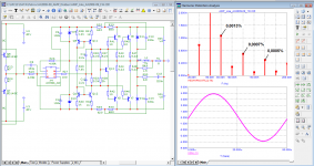
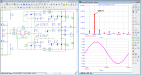
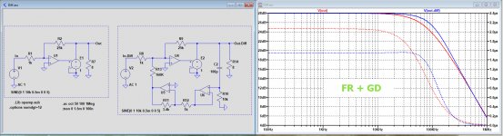
In the two images below you see a simple amp with a 70Khz BW and the same amp with the feedback added from a differentiator.
With differentiator FR is extended to 100Khz, but the GD between both versions is quite different.
With differentiator is goes down from 2.1usec to 1.5usec and has a much larger frequency span.
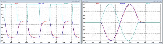
When processing a square wave or a 20kHz frequency burst, the difference are quite noticeable.
Hans
You might have thought that I was kidding when mentioning the option for a PID control system.
Well, I was not.
In the two images below you see a simple amp with a 70Khz BW and the same amp with the feedback added from a differentiator.
With differentiator FR is extended to 100Khz, but the GD between both versions is quite different.
With differentiator is goes down from 2.1usec to 1.5usec and has a much larger frequency span.
When processing a square wave or a 20kHz frequency burst, the difference are quite noticeable.
Hans
Attachments
- Home
- Amplifiers
- Solid State
- Musings on amp design... a thread split