as for the amplitude of the multitone signal, then it is chosen so that the peak signal levels do not reach the level at which clipping occurs
That paper now makes more sense. I took some time to review it, have some comments.
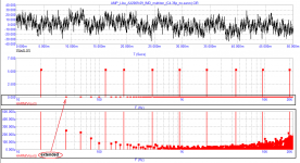
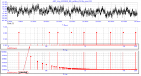
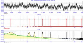
In the comparison between fig 2 and fig 3, in fig 3 the FFT floor is higher at low frequencies than in fig 2. Your conclusion is that the LF noise is higher. But to me it looks like you have a very wide FFT resolution (only very few bins). So, like in fig 5, it is impossible to see the LF noise between the two main bins of 20Hz, 120Hz I think it is. You just don't see the noise so you don't know what it is.
Regarding the noise level comparison between fig 6 and 7, the noise levels in the lower graph (if it is noise) are the same, but in fig 7 there is a DC drift over time which is consistent with the large time constants in the servo circuit and which will eventually stabilize. There is no noise difference between fig 6 and fig 7.
Jan
PS If you want to make it easier for readers to follow you, delete the middle part with the screen shot. Only distracting and not important to the point you are trying to make. Secondly, do not mix the C4 stuff with the servo stuff. You are trying to tell us something about the servo, then concentrate on that. With this in mind your paper gets 2/3 shorter, more focused and more powerful. Free advice.
Last edited:
Jan,
My reaction is identical to yours.
We are not looking at noise but at IM products, which should not at all be confused with noise.
Bins are much too wide and the narrower the bin, the more spectra should be averaged to get a reliable view on the noise.
Frequencies are OK, no comment on that.
The servo used is a second order filter which is not recommended for this type of application and besides the position where it takes it’s gnd reference is very critical and may contribute to a great deal to the recorded anomalies.
BTW Petr: what happened to the GD issue, I was under the impression that you were convinced that this played a major role in this all ?
Hans
P.s. The servo has unequal impedances at it’s input. The positive side should also see 1Meg//1uF
Last edited:
That is not a logical conclusion.billshurv, your test is as bad as the previous test with frequencies over 1 kHz. This multitone has 30 frequencies. The more frequencies the lower their levels. The lower the levels of the RF components of the signal, the less the likelihood of intermodulation and velocity distortion.
Nope, AP are not stupid enough to have the IMDs falling on a multitone frequency.The frequencies are extremely poorly chosen, most of the first order intermodes (having the maximum level) fall on the multitone frequencies. For example, 15 kHz - 12.5 kHz = 2.5 kHz; 15 kHz - 10 kHz = 5 kHz; 12.5 kHz - 10 kHz = 2.5 kHz; 10 kHz - 8 kHz = 2 kHz; 8 kHz - 6.5 kHz = 1.5 kHz; you can count in the reverse order: 10 + 5 = 15; 10 + 2.5 = 12.5; 12.5 + 2.5 = 15; 8 + 2 = 10 and so on ...
Attached 18+19k for the same amplifier. Gobs of feedback, no problem 🙂So use simple CCIF, 19+20kHz. Or use e.g.50+51kHz and look for product at 1kHz.
as for the amplitude of the multitone signal, then it is chosen so that the peak signal levels do not reach the level at which clipping occurs
Test signal chosen to not clip the DUT. Blimey who would have expected that. In this whole tortured thread we have not been discussing clipping. Why bring it up now.
Attachments

This is not a spectrum.
It is a bunch of red lolly pops.
Send me the time signal and I will do a spectral analysis.
Hans
It is a bunch of red lolly pops.
Send me the time signal and I will do a spectral analysis.
Hans
This is not a spectrum.
It is a bunch of red lolly pops.
Send me the time signal and I will do a spectral analysis.
Hans
Hans, finish one job first. You promised to test two amplifiers with a multitone and lay out all the parameters. I asked at the same time to lay out their schemes, so that you could then compare the test results in hardware with virtual ones.
Petr,
It seems you are avoiding the confrontation.
Not a good outlook for future results.
Results are invalid when not reproducible by a at least one independent someone else.
Hans
It seems you are avoiding the confrontation.
Not a good outlook for future results.
Results are invalid when not reproducible by a at least one independent someone else.
Hans
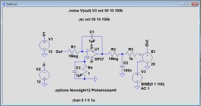
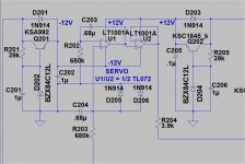
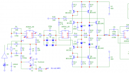
I simulated the Servo that was used in your example.
First image shows the Circuit Diagram, for an amp with a gain of 20.
In your Baxandall example you multiply the input signal with 18.9, but to my opinion it should be 1+4700/249= 19.9.
After having settled, no sign of any DC shift in the output was noticeable, no matter what offset I gave the input source.
So it must be the main amp in your case that is shifting DC, or a badly chosen gnd connection point for the servo, so be careful, one swallow doesn't make a summer.
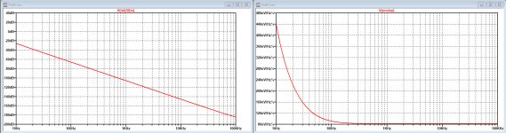
The left part of the second image shows how much counter signal is produced by the servo compared to the input signal.
It's no wonder that in your images where [input signal * gain -/- output signal] is showing a severe ramp up at LF with this Servo connected.
And this has nothing to do with GD, just straightforward feedback from the Servo.
Second image right part shows the output noise caused by the Servo.
Same thing here, at LF noise is increasing rapidly.
The important question of course is: does a Servo harm to the reproduced sound.
I don't think so, whatever happens will be absolutely inaudible and after applying A-Weighting, it becomes even totally insignificant.
So to my opinion you are on the wrong way when blaming a servo and I see no connection whatsoever to GD.
Hans
First image shows the Circuit Diagram, for an amp with a gain of 20.
In your Baxandall example you multiply the input signal with 18.9, but to my opinion it should be 1+4700/249= 19.9.
After having settled, no sign of any DC shift in the output was noticeable, no matter what offset I gave the input source.
So it must be the main amp in your case that is shifting DC, or a badly chosen gnd connection point for the servo, so be careful, one swallow doesn't make a summer.
The left part of the second image shows how much counter signal is produced by the servo compared to the input signal.
It's no wonder that in your images where [input signal * gain -/- output signal] is showing a severe ramp up at LF with this Servo connected.
And this has nothing to do with GD, just straightforward feedback from the Servo.
Second image right part shows the output noise caused by the Servo.
Same thing here, at LF noise is increasing rapidly.
The important question of course is: does a Servo harm to the reproduced sound.
I don't think so, whatever happens will be absolutely inaudible and after applying A-Weighting, it becomes even totally insignificant.
So to my opinion you are on the wrong way when blaming a servo and I see no connection whatsoever to GD.
Hans
Attachments
Last edited:
Petr, to make things even more obvious, I have drawn the added signal from the integrator into your suggested distortion graph with a green line.
The signal on this green line, being the difference between input*gain minus output signal has absolutely nothing to do with any distortion at all, it is just a strictly linear feedback process from the integrator.
Given the low levels and the LF frequencies that are concerned, we may safely assume that possible distortion from this integrator's signal is at way below any detectable level.
Hans
Attachments
I think that if you look at the frequency response at the output of the servo, you will see this exact curve.
1Meg & 1uF is a 1 sec RC time, so you will get appreciably servo output at low frequencies, inserted at a high gain point.
Jan
1Meg & 1uF is a 1 sec RC time, so you will get appreciably servo output at low frequencies, inserted at a high gain point.
Jan
I like post #310.
Another R/C on the + op-amp input ??
I use this (below -VFA). Real tested amps drop at about 6hz. uV offset.
I use the non-inverting version for CFA's , positive FB with R204 = 270k (to the
non- inverting CFA diamond pair).
About 3 ppm "hit" at LF on a VFA , nothing on the CFA.
I'll have to simulate post 310 , see if it's better .... 😀
OS
Attachments
I don't know how you got fig 2, what were the input and output, but it cannot be the servo transfer function, as that is an integrator.
Also, again, the use of a music signal is very confusing as we don't know what frequencies and levels are used, and how it corresponds with the time scale of the other graphs.
You have a great talent for obscuring the test conditions to prevent us from understanding what's going on.
Jan
Also, again, the use of a music signal is very confusing as we don't know what frequencies and levels are used, and how it corresponds with the time scale of the other graphs.
You have a great talent for obscuring the test conditions to prevent us from understanding what's going on.
Jan
Last edited:
I explain for those who did not understand
The operational amplifier uses 2 inputs:
pin 5 - useful signal input;
pin 3 - servo control signal input;
By grounding the input of the useful signal, you can remove the frequency response from the input of the servo control
The operational amplifier uses 2 inputs:
pin 5 - useful signal input;
pin 3 - servo control signal input;
By grounding the input of the useful signal, you can remove the frequency response from the input of the servo control
Attachments

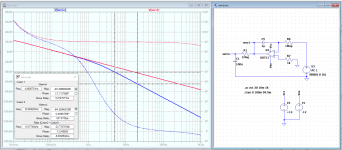
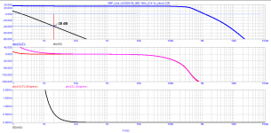
I did a quick servo sim, see attached. Similar circuit as Petr's.
The gain of the circuit at 5Hz is -40dB, at 20Hz it is -64dB.
Let us assume that the amplifier gain is 26dB, a normal number. That means that at 5Hz, the servo signal is -14dB with respect to the input signal. At 20Hz, it is -38dB with respect to the input signal.
This should be very visible in an FFT as mentioned by Hans before.
Makes sense?
Jan
Attachments

OK, I see. No surprises here.
Are you going back to your FFT graphs again?
That was what the discussion was about, no?
Jan
Are you going back to your FFT graphs again?
That was what the discussion was about, no?
Jan
- Home
- Amplifiers
- Solid State
- Musings on amp design... a thread split