Show simulation outside class A region (output power 10-50W) and with realistic ( complex, with capacitive part..)load... No with such idealized , but unrealistic conditions..🙄 And also real measurements.
Last edited:
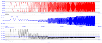
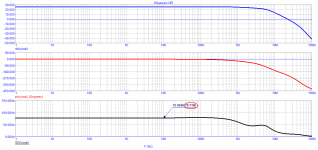
The effect of capacitors (bandwidth at the bottom) can be traced in the following tests
a constant component of more than 50 mV appears at the output
a constant component of more than 50 mV appears at the output
Attachments
As mostly the case, the images are hard to understand without explanatory text, but even without images it is easy to understand why DC appears at the output. It’s because input current of the 2N5401 is not symmetrical.
You are right that this output DC should better be prevented.
But is has no relation to aiming for a very low and flat GD that you favour.
Hans
You are right that this output DC should better be prevented.
But is has no relation to aiming for a very low and flat GD that you favour.
Hans
Yes, Hans, you rightly noticed that I am a supporter of the most flat characteristics of the GDelay. This also corresponds to the theory according to which, for the transmission of any signal with minimal distortion, the frequency response and phase response should be as linear as possible, and therefore must be linear and the group delay
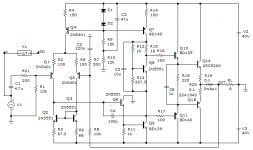
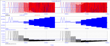
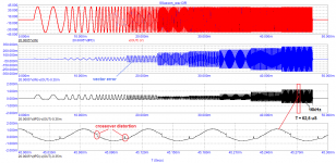
Here is an example of a test of an amplifier model from a neighboring branch (from which my posts were uploaded here)
Ku tuned in at a frequency of 10 kHz. The test shows that at a frequency of 16 kHz, Ku has changed slightly and the signal suppression is incomplete.
In the low-frequency region, the second harmonic prevails, and it is mainly distinguished as a product of distortion.
Attachments
Changes in frequency response or phase response is linear distortion and does NOT generate harmonics.
Non-linear circuit elements cause non-linear distortion which DOES create harmonics.
Jan
Non-linear circuit elements cause non-linear distortion which DOES create harmonics.
Jan
«Changes in frequency response or phase response is linear distortion and does NOT generate harmonics.»
This is true for only one frequency in the steady state. At the beginning of the period there is a transient process (I have shown it many times), and also when the signal amplitude changes or when its frequency changes, a transient process also occurs. The concept (term) "linearity" does not refer to transients.
Therefore there is no correlation between THD and sound quality
Only happen in simulation. You still do not understand, probably because you do not know how to measure. Recorded signal does not have that.... At the beginning of the period there is a transient process (I have shown it many times), and also when the signal amplitude changes or when its frequency changes, a transient process also occurs...
«Changes in frequency response or phase response is linear distortion and does NOT generate harmonics.»
This is true for only one frequency in the steady state.
No. It is the DEFINITION, you can't just change the meaning of words because it suits your purpose. Linear distortion does NOT generate harmonics.
Therefore there is no correlation between THD and sound quality
There is no 'therefore' in your post. 'Therefore' is referring to a cause, that results in something. You did not mention any cause for the result 'there is no correlation between THD and sound quality', although the statement is often, but not always, correct.
Jan
Only happen in simulation. You still do not understand, probably because you do not know how to measure. Recorded signal does not have that.
We have explained to him many times that real world signals never start (or stop) in infinitely short times.
However, that takes the whole bottom out for his frivolous case, so he prefers to continue to believe in something that is wrong.
Jan
It's hopeless.
I know. On the other hand, you can't just let someone continue to spread incorrect and wrong stuff.
Jan
Yes, transients can cause harmonics. Because ALL signals will cause harmonics if there are non-linear elements in the circuit. It is called 'non-linear distortion'. What is your point?
Jan
Jan
Jan, read the right textbooks with the right theory
When I can find the time in the next week, I will do a multitone test instead of a sim, with increasing levels for two completely different amps with 8R load.
I will of course also measure their GD.
Will 20 tones do from 100Kz to 10Khz ?
Let's see what happens, two possibilities:
1) the noise floor will increase as you have suggested.
2) the noise floor will not increase, but several IMD products will become visible.
Hans
Anybody who knows how to measure will not make this kind of silly mistake.However, that takes the whole bottom out for his frivolous case, so he prefers to continue to believe in something that is wrong.
IT is strange (or not so) that the models of devices show noise while at rest .
(below)
Real units show +/- .4 mv. I'm servo'ed , so F all. I can't hear it on my silk dome tweeters , I am happy.
" Hypothetical signals" - this discussion seems to be mostly subjective.
Signals are real ...
OS
(below)
Real units show +/- .4 mv. I'm servo'ed , so F all. I can't hear it on my silk dome tweeters , I am happy.
" Hypothetical signals" - this discussion seems to be mostly subjective.
Signals are real ...
OS
Attachments
Last edited:
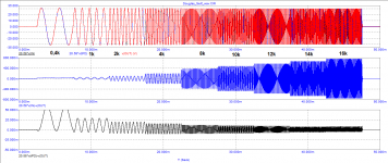
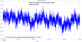
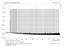
Real measurements ,my amp, multitone signal..Output attenuated cca 30dB. Amp with total GD (inclusive input LP) about 450ns. Amp alone about 210ns. This is reality, no "strange" theory.
Attachments

Last edited:
So ARTA can generate multitones? Didn't know that, that's interesting.
I wonder if the crest factor and individual phases can be specified.
Need to check it out.
Jan
I wonder if the crest factor and individual phases can be specified.
Need to check it out.
Jan
- Home
- Amplifiers
- Solid State
- Musings on amp design... a thread split