And they were built with much slower output devices...
Perhaps that's why the Russian diyers prefer the TEF BJT outputs.
We will see...
My initial impressions (based on oscilloscope waves) are very good.
To me this should be the best (so far) from all 'unusual' amps.
Also the sim matches the reality very closely. There was no need to tweak anything, as far compensation/stability goes (only the bias spreader thing).
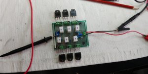
Also the PCB seems to be OK - there are always issues with possibility of oscillations with multiple pairs of fast fets... But here all works just fine, especially with relatively low values for gate stoppers.
The same PCB can acomodate new bias spreader, I just had to cut one trace...
My initial impressions (based on oscilloscope waves) are very good.
To me this should be the best (so far) from all 'unusual' amps.
Also the sim matches the reality very closely. There was no need to tweak anything, as far compensation/stability goes (only the bias spreader thing).
Also the PCB seems to be OK - there are always issues with possibility of oscillations with multiple pairs of fast fets... But here all works just fine, especially with relatively low values for gate stoppers.
The same PCB can acomodate new bias spreader, I just had to cut one trace...
Last edited:
Mosfet matching process will be time consuming - waiting for them to cool and combining matching ones (pairs/triplets) and re-testing them, but I hope the results will be worth it....
Attachments
Last edited:
I simulated your latest circuit with IRFPs, but its high frequency behavior was not as good as with FQAs. So I prefer to order them from mouser, leaving the IRFPs for other projects.
Hugh, on the other hand, mentioned an interesting point somewhere about FQAs:
"I have used FQA36P15 and FQA40N25.These are not well suitable to audio, but their 300W Pd rates and their cheap make them attractive. Both have high gm, around 30S. It is mandatory that 47R and 220pF series snubber between gate and drain to prevent cross conduction. Powerful gate drive is required, but they perform well."
Maybe useful info here as well.
Last edited:
I used FQAs before (as well as FDAs).
I have 4 amps here, still in use, built with them.
In this amp I actually used FQA27N25 + FQA36P15.
It is true that it's easy to get them to oscillate, but at least in my cases - these snubbers didn't help. I experimented with them a lot.
Don't need to worry if you are going to only use 1 pair, they will be fine.
If using multiple pairs -
the most important thing to prevent oscillating is good matching, and of course good PCB design.
That's why I think this current amp behaves very good, comparing to other multi-pair-mosfet amps I built.
Most of audio sources (e.g. DACs I'm using) have a cap at the output, so I doesn't really matter if this input cap is there or not..., they will not be directly coupled anyway...
After 3 hours of matching mosfets, finally came up with 2 sets of triples for N mosfets.
They still not perfect, but they will work. My new part-time job - human curve tracer 🙂
Now trying to get P ones matched..
After 3 hours of matching mosfets, finally came up with 2 sets of triples for N mosfets.
They still not perfect, but they will work. My new part-time job - human curve tracer 🙂
Now trying to get P ones matched..
Last edited:
Great news. Looking forward to the result. Meanwhile I decided I'm going to order FQA46N15/FQA36P15 instead of FQA27N25/FQA36P15. These FETs are able to drive very low impedances well below 2Ohms.
I have modified my theory.
After spending 2 days with different methods of matching mosftes, the conclusion is that the mosfets WERE matched OK.
More or less. Perhaps not perfect, but definitely they should nicely co-operate sharing current.
They didn't.
Observations:
1) amp with 1 pair worked flawlessly
2) amp with 2 pairs wasn't tested
3) matching rig from post #1516, when used to match 2 mosfets was showing acceptably close match for most of the pairs.
4) same rig - when used to match 3 mosfets was showing strange behavior - sometimes 1 mosfet hogging 75% of the current
5) same behavior could be observed in the amp, when 3 pairs supposedly matched mosfets were installed.
1 or 2 pairs - good, 3 pairs - bad.
So, since the matching was more or less correct, the only explanation would be that SOME mosfets were wildly oscillating.
None of these oscillations were observable on the oscilloscope.
Amp was always working fine, showing accurate waves.
What is to be done?
I guess first I will try increase gate stoppers to higher values, say 100 Ohm.
While at it, it seems that N and P devices have 33% difference in input capacitance (according to the sheet). This I'll verify by measurements, especially that I remember seeing much higher Ciss number than the sheet shows, last time I measured them. I guess sheet's number might be too optimistic..
So N gate stopper gonna be 125 Ohms, and P stopper 80 Ohms.
Let's see if this helps.
If it doesn't, there 2 are more options:
1) increase gate stoppers resistance even further
2) use RC network as recommended by Hugh back in 2012.
This I have tried before on 2 amps, and it didn't help. But who knows.
Hugh usually knows his stuff... So it's worth trying.
Any other suggestions?
Good thing I have more PCBs; at this rate of experimentation and destroying boards, I'm gonna go through them like sh..t through the goose.
And I need to order more solder wire and desoldering wick 🙂
That's what happens when lack of knowledge, professionalism and experience is combined with too much time on my hands.
Update: measured Ciss on FQA27N25 is 3 nF, and on FQA36P15 is 5.4 nF
Last edited:
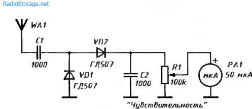
An externally hosted image should be here but it was not working when we last tested it.
With an increase in the number of transistors, the nonlinear capacitive load of the Vas (drivers) increases. This can lead to generation at frequencies up to tens of MHz. Radio emission can be detected using the simplest "bug" indicator.
Last edited:
I like this design because it keeps the drive to the VAS single ended.
This promotes H2 over H3, and MOST people prefer dominant H2.
Very nice design, Minek, and you are indefatigable.........
HD
This promotes H2 over H3, and MOST people prefer dominant H2.
Very nice design, Minek, and you are indefatigable.........
HD
Very nice design, Minek, and you are indefatigable.........
HD
100% agree. He does a very important work and treads unfamiliar roads. However, I have interesting experience with common base VAS. I built two such amplifiers: VHEX + (single ended) and PHLIPS AH578 LATFET (symmetrical). Both sound very clear, there is no sign of "scratch" in sound. HVEX + is indeed H2 dominant with a beautiful decreasing fft profile, while PHILPS is odd dominant and not only does the amplitude of the higher harmonics not decrease, but it even rises in some points. Still, PHLIPS have much warmer, tube-like sound than VHEX+. I don’t really understand that. But this difference is clear. APEX B500 with otherwise BJT output sounds very similar way, so I don't think LEATFETs cause this warmness itself.
Last edited:
Ok, so I changed the gate stoppers (120 and 82 Ohms), and also removed 'speed-up cap' between emitters of the drivers.
Amp has been idling for 3 hours, current sharing is ok - within 20% on each fet.
So far so good. Idle current very stable, while temperature changes.
The new spreader works like a champ.
This afternoon will continue tests with waves and more power.
Not sure about this 'speed-up' cap. Does it even belong to mosfet OS?
I see some designs use it, most don't.
Last edited:
>You mean 2x2N3904?
Yes.
It doesn't have to be 2N3904.
Anything similar will work too. Tried MPSAs as well, but I have lots of 2N3904s, that have to go 🙂
Yes.
It doesn't have to be 2N3904.
Anything similar will work too. Tried MPSAs as well, but I have lots of 2N3904s, that have to go 🙂
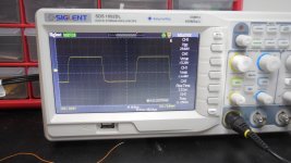
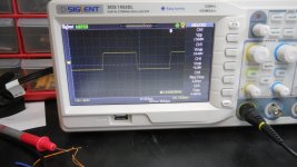
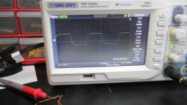
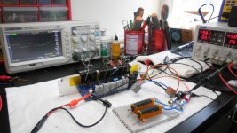
More tests completed. See screenshots.
Everything works fine.
One time I forgot to connect the thermal sensor transistor-diode wires, and bias skyrocketed to the max amperage.
Somehow the amp survived 🙂
So to prevent such events in the future, I added 9.1V Zener across the spreader. This will limit idle current to approx 300mA in case of spreader failure.
Most current sim file attached.
When looking at square waves, check out the 'rise_time' displayed by the oscilloscope, rather than looking at rounded edges of squares - their 'roundness' depends on Vpp and screen scale, which may not be perfect..
This amp - because of 3 pairs of output devices - is running too hot for this small test heatsink. More tests at higher power will follow, when this thing is mounted on the proper chassis with bigger heatsink.
Looking back at first LMK amp square waves results, rise_time is definitely higher - if this can be an indicator of most likely higher slew rate of this amp. Same goes for Wiederhold amp builds.
BUT - Philips amp was even faster, with higher rise_time numbers.
All in all, I went through 3 prototypes, on 3 PCBs, and I burned 1 mosfet (I touched something on the board with a screwdriver during square wave test..).
I guess this is as good as it gets.
So more tests to follow (including audio analyzer tests) after this build is finished, heatsinked, and powered by bigger PSU.
On this PSU with limited amps, I'm unable to reach real clipping behavior.
Perhaps while I have it on the test bench, I should test different op-amps. This build is using actual LT1056.
Attachments
-
 DSCN0573.JPG259.7 KB · Views: 235
 -
 DSCN0575.JPG259.6 KB · Views: 164
 -
 DSCN0580.JPG264.4 KB · Views: 163
 -
 DSCN0581.JPG263.1 KB · Views: 158
 -
 DSCN0584.JPG262 KB · Views: 186
 -
 DSCN0585.JPG282.4 KB · Views: 248
 -
lmk_hexfet.50v.beast.asc15.3 KB · Views: 111
-
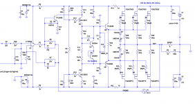 lmk_hexfet.50v.beast.png118.1 KB · Views: 352
 -
lmk_baby_beast_pcb.zip45.4 KB · Views: 163
Last edited:
The following JFET op-amps has been tested:
LT1056 - works fine (as in the sim)
TL072 - works fine
TL2081 - works fine
TL2071 - works fine
OPA 134 - works fine
AD711 - works fine, BUT I see _possibly_ some little oscillations at the bottoms of squares
LF356 - NO
LT1357 - NO
All in all, that's pretty good. Previous builds of similar amps would NOT work with so many different op-amps (without tweaking compensation).
So I guess this suggests it's a stable amp.
I tested these other op-amps with 1kHz sinus and square and with 10kHz sinus/square.
No differences in the waves were observed, as far as I can tell, all these op-amps were behaving the same.
One more thing to mention - output DC offset starts at 10mV and settles down at 5mV.
Last edited:
 Congratulations for your latest amp. Good to see how many opamps this circuit works with. BTW I think it is relative easy to eliminate oscillation at AD711. Place 100nF capacitors as close to the opamp supply rails as possible (2-3mm) and lead them to the star point with separate ground tracks (I used a similar layout on the A578 PCB)
- Home
- Amplifiers
- Solid State
- Unusual amp from 1987