That's what Akulinichev claimed.. But is it true?
See more or less skeptical reactions to these claims in the beginning of this thread.... From people who know what they're talking about. At least that was my feeling..
If it was so good, why nobody is using it? Even Maxim rejected it 🙂
It can be simulated, but I've never done _temperature_ simulations..
Perhaps it's easier to build it, and adjust tempco empirically.
OK I accept that. It was just an idea. At some point in a previous simulation, it showed noticeably better results compared to the conventional bias spreader, especially the high order odd harmonics were lower. Of course, I don't know what it means in practical terms.
I was testing yesterday and today the amp from post #1470.
So far no luck. Un-explainable behavior, very difficult to track down..
I re-soldered everything twice already, checked and replaced every active device several times, tried different devices, spreaders, compensations, etc...
Didn't give up yet, but I'm close...
That's why I'm investigating Akulinichev spreader for Mosfets - perhaps will try to build Mosfet LMK amp (like the BJT one built as the first one in this thread),
re-using PCBs I have for the BJT version. If I can get that spreader to work, I only need to add gate stoppers, and everything else on the PCB will fit just fine.
As an experiment...
I already built/tested a while ago an LMK amp with hexfets, but without drivers.... It worked, was stable, but sound was not that great...
And that was with traditional Vbe multiplier... Not sure why I didn't try with drivers while I was at it....
Also that amp was done with IRFP outputs. The latest one is using FQAs..
Attachments
Last edited:
No, the whole amp immediately draws enormous current, the rails are collapsing from 50V to 5V when current limiter in PSU kicks in. So I can't even measure anything. If I enable unlimited current something gonna burn (e.g. LEDs, or surprisingly bias spreader did burn on different occasions) very quickly..
With limit set to 100mA nothing gets burned at least...
Must be some kind of nasty oscillation somewhere.
It all happens fast, so nothing even gets hot. Surprisingly FQAs survived all this abuse so far...
I suspected a mistake in pcb, or in soldering - that would be most likely source of problems, but I re-checked everything million times already.
Well, I'll let it sit for a week, and then think about it again.
Last edited:
Akulinichev's shunt was used only with BJT.
Mosfet amplifiers can have high inrush (through) currents during transient.
The amplifier may have insufficient stability margin if the correction is not optimal.
Mosfet amplifiers can have high inrush (through) currents during transient.
The amplifier may have insufficient stability margin if the correction is not optimal.
Last edited:
>I was testing yesterday and today the amp from post #1470.
>So far no luck. Un-explainable behavior, very difficult to track down..
OK, the problem has been found, and amp from post #1470 is working like a champ.
After all this re-soldering and testing, the PCB is garbage now. The champ looks like he was hit by a bus.
Will make new build, and repeat the exercise, most likely next weekend.
"Experience is simply the name we give our mistakes" - Oscar W.
Attached are my "experiences" from last 2 years.. This box is deeper than it looks..
Attachments

Last edited:
>I was testing yesterday and today the amp from post #1470.
>So far no luck. Un-explainable behavior, very difficult to track down..
OK, the problem has been found, and amp from post #1470 is working like a champ.
After all this re-soldering and testing, the PCB is garbage now. The champ looks like he was hit by a bus.
Will make new build, and repeat the exercise, most likely next weekend.
"Experience is simply the name we give our mistakes" - Oscar W.
Attached are my "experiences" from last 2 years.. This box is deeper than it looks..
What was the problem?
I hope the parts on those PCB's get recycled!!
Yes. Sad to see those expensive Bourns trimpots in the garbage. I would get them out of there.
What was the problem?
I hope the parts on those PCB's get recycled!!
There was a mistake on the silkscreen (PNP marked instead of NPN), and I was aware of this, but since it was a while ago when I designed PCBs, I forgot about it, and I assumed silkscreen was correct...
Damn memory..
These parts will get recycled, when I have more time..
Tested the new build on new PCB - first with 1 pair, and then with 3 pairs.
Observations:
1) Amp works fine. Consistent with LMK/Wiederhold builds, but faster slew rate. Stable.
Great performance on the oscilloscope. Perfect square waves. Lots of power.
Didn't test with music yet.
2) Fet matching was not good. When checking voltage on source resistors, differences are from 20% to 100%. These _actual_ results are totally disconnected from my matching results..
This observation is consistent with my previous experience with matching fets. Very unreliable process. When I repeated the _same_matching procedure the next day, with the same devices, the results were totally different (random??).
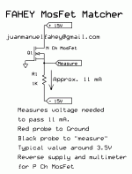
The method I use - attached here (I was matching at 10 and 100mA).
3) NTC thermal tracking is bad. It needs either serious re-calculation of the values for NTC/resistors, or the whole spreader needs to be changed to use 'normal' transistor sensing temperature + LED.
It drops bias way too much and too quickly.
Will deal with bias spreader first, and then try to match fets again.
Observations:
1) Amp works fine. Consistent with LMK/Wiederhold builds, but faster slew rate. Stable.
Great performance on the oscilloscope. Perfect square waves. Lots of power.
Didn't test with music yet.
2) Fet matching was not good. When checking voltage on source resistors, differences are from 20% to 100%. These _actual_ results are totally disconnected from my matching results..
This observation is consistent with my previous experience with matching fets. Very unreliable process. When I repeated the _same_matching procedure the next day, with the same devices, the results were totally different (random??).
The method I use - attached here (I was matching at 10 and 100mA).
3) NTC thermal tracking is bad. It needs either serious re-calculation of the values for NTC/resistors, or the whole spreader needs to be changed to use 'normal' transistor sensing temperature + LED.
It drops bias way too much and too quickly.
Will deal with bias spreader first, and then try to match fets again.
Attachments
After little experimenting at different power levels (temperature) with the amp,
this biasing seems to work the best for FQA mosfets.
Idle current is kept stable at different temperatures.
Will test later on with bigger PSU, to check on higher power levels.
As for the supposedly matched mosfets, these are the values of voltages on source resistors (0.33 Ohm) on 3 pairs:
N: 11mV
P: 9
N: 14
P: 10
N: 11.5
P: 21
I guess tomorrow will replace the last P mosfet.
Not sure if these numbers are ok, or more even numbers are needed...
I remember several people saying that mosfets coming from the same batch will be matched 'close enough'.
After trying to match mosfets from several batches, it seems to me that above statement is not true.
Mosfets from the same batch actually vary a lot.
Attachments

Last edited:
Amp is stable and working great.
The only remaining issue is mosfet matching.
I found one thing - there is big difference when matching/measuring mosfets
on the common heatsink, vs no heatsink, when each mosfet can run at different temperature.
E.g. when measuring voltage drop on source resistors when amp is cold, variations of voltages on all 6 fets are huge. When heatsink warms up, the differences become smaller. But generally speaking, the voltage drop is VERY dependent on the temperature.
When doing the same test WITHOUT heatsink, differences will remain, and even become BIGGER as each mosfets will have different temp.
I'm thinking about setting up a rig to match mosfets, in such a way that it would mimic output stage of the amp as close as possible.
Plug in mosfets (without heatsinks, and later on common heatsink), let it boil for 10 minutes, and then measure voltage drop on each resistor.
I don't care about absolute value of the drop, as long as I can select 3 pairs with _the_same_ drop.
Attachments

>How did you achieve 62V/us SR? Previous LMKs did not go above 20V/us.
In sim - yes.
In real amp - I didn't run tests at full amplitude yet, because mosfets are not matched yet...
In sim - yes.
In real amp - I didn't run tests at full amplitude yet, because mosfets are not matched yet...
I suspect previous LMK amps were underestimated as far as SR goes...
And they were built with much slower output devices...
And they were built with much slower output devices...
- Home
- Amplifiers
- Solid State
- Unusual amp from 1987