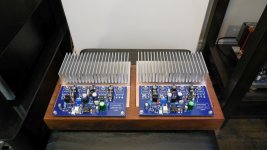
Mosfets matched, amp ready for testing. Will try to do it this weekend..
The idea is that 2 amps will be bolted to 1 heatsink, as shown, one next to each other, and - as usual - whole thing gonna be mounted on top of chassis (this time - wood (African Acacia), not Alu).
Assuming the testing will go well 🙂
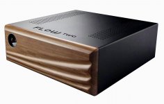
Sometimes a wooden case can be really beautiful. Sometimes the front panel too. See the amplifier below. Made in Hungary.
Attachments
I was trying to track down the origins of 'so called' Wiederhold '77 topology. The first ocurrence I was able to find, was of course Wiederhold's article in German magazine "Radio Fernsehen Elektronik" from 1977.
As it was pointed by Ian Hegglun, this topology dates back to at least 1962, when it was described by James Faran and Robert Fulks in the article for IRE (Institute of Radio Engineers) "High-Impedance Drive for the Elimination of Crossover Distortion" (attached) while they were working for General Radio Company.
The output stage of their amp is different, but the principle of the interactions between input and voltage amplification is described.
The overall characteristics (E.g. the Thd) of their amp are phenomenal, given it was done in 1962.
Attachments
At the end of Wiederhold's article in RFE, there is a list of references. I was unable to trace some of the sources. Reduction of crossover distortion is achieved by deep overall feedback with optimal correction. Viderhold Topology: OPamp + level shifter stage (EF + CB) + Vas(CB) + kvazikomlimentarny outputstage.
Last edited:

"High-Impedance Drive for the Elimination of Crossover Distortion" - In the Russian radio magazine, this concept is called "transistor current control".
Усилитель Дорофеева – режим “В” в усилителях мощности | ldsound.ru
Я. Будинский. Усилители низкой частоты на транзисторах.— М.: Энергия, 1963.
К. Качурин. Токовое управление оконечным каскадом усилителей НЧ.— Радио, 1967, № 9, с. 32, 33.
В. Демьянов. Широкополосные усилители на триодах.— Радио, 1966, № 10, с. 50—53.
В. Демьянов, И. Акулиничев. Резонансные усилители на лампах и транзисторах.— М.: Энергия, 1970.
С. Бирюков. Усилители мощности низкой частоты. Авторское свидетельство СССР № 315267, класс H03F3/18.— Бюллетень «Открытия, изобретения, товарные знаки», 1971, № 28.
А. Майоров. Динамические искажения в транзисторных усилителях НЧ.— Радио, 1976, № 4, с. 41, 42.
М. Дорофеев. Приставки для измерения коэффициента гармоник.— Радио, 1990, № 6, с. 62, 63.
Автор: Дорофеев М., по материалам: журнал “Радио” №3, 1991 год
Стр. 33 журнала <<Радио>> № 9 за 1967 год
Last edited:
Thanks OldDIY!
In my searches in Russian materials, I didn't go that far back (before 1975)...
In my searches in Russian materials, I didn't go that far back (before 1975)...
"High-Impedance Drive for the Elimination of Crossover Distortion" - In the Russian radio magazine, this concept is called "transistor current control".
...
Edge will translate for you:
"High-Impedance Drive for the Elimination of Crossover Distortion" - In the Russian radio magazine, this concept is called "transistor current control".
Dorofeev amplifier – mode "B" in power amplifiers | ldsound.ru
J. Budinsky. Low-frequency amplifiers on transistors.— M.: Energiya, 1963.
K. Kachurin. Current control of the terminal stage of amplifiers LF.— Radio, 1967, No 9, pp. 32, 33.
V. Demyanov. Broadband amplifiers on triodes.— Radio, 1966, No 10, pp. 50-53.
V. Demyanov, I. Akulinichev. Resonance amplifiers on lamps and transistors.— M.: Energiya, 1970.
S. Biryukov. Low frequency power amplifiers. USSR Author's Certificate No. 315267, class H03F3/18.— Bulletin "Discoveries, Inventions, Trademarks", 1971, No 28.
A. Mayorov. Dynamic distortion in transistor amplifiers LF.— Radio, 1976, No 4, pp. 41, 42.
M. Dorofeev. Prefixes for measuring the harmonic coefficient.— Radio, 1990, No 6, pp. 62, 63.
Author: Dorofeev M., based on the materials: magazine "Radio" No3, 1991
Page 33 of the journal <<Radio>> No 9 for 1967
Sounds like the old idea that High-Z VAS will jump across the cross-over region due to the high-Z input of the drivers in that region. It works but is limited by natural CB capacitance in the VAS and prevents adding miller caps. The global feedback has to be a small loop. Maybe a cascode VAS would help.
More interesting is the variation on CFP outputs that 1: cross-couples CE outputs and 2: uses AC only local feedback.
The 1st item on the "Literature" list in Wiederhold's article, is a book written 50 years ago by Tietze and Schenk: "Advanced Electronic Circuits".
As it happens, this book is still in print (I hope with updates..), and supposedly used at universities..
Authors describe this topology exactly as it is implemented in Wiederhold and Lomakin/Parshin amps. Here is page 168 attached.
As it happens, this book is still in print (I hope with updates..), and supposedly used at universities..
Authors describe this topology exactly as it is implemented in Wiederhold and Lomakin/Parshin amps. Here is page 168 attached.
Attachments
The 1st item on the "Literature" list in Wiederhold's article, is a book written 50 years ago by Tietze and Schenk: "Advanced Electronic Circuits".
As it happens, this book is still in print (I hope with updates..), and supposedly used at universities..
Authors describe this topology exactly as it is implemented in Wiederhold and Lomakin/Parshin amps. Here is page 168 attached.
Why do LF and HF have separate signal paths? Maybe because of the limited bandwidth of the opamp?
Why don't you use Akulinichev's bias spreader anymore? According to my memories, its high-frequency behavior was noticeably better than that of the ordinary bias circuit. It has a good effect on the crossover distortion of output FETs as well. As I saw on the vegalab there are several 2Si versions.
Attachments
The spreader with thermistor is specifically designed to work with mosfet tempco, and I used/tested it before in other mosfet amps. Works very well.
I would still use Akulinchev spreader for BJT amps. Even with Germanium transistors (which I still have) 🙂
Don't know how Akulinchev spreader behaves with mosftes...
Havnt's seen any russian mosfet amps with Akulinchev spreader...
Also, I have 1k resistor between gates, A. spreader would require adaptation/recalculation.
Last edited:
Why do LF and HF have separate signal paths? Maybe because of the limited bandwidth of the opamp?
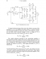
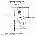
Yes. The concept goes back well before the LM318 opamp datasheet.
http://www.mit.edu/~6.301/LM118.pdf
If you follow the internal plan, the 0.1u cap dumps signal in after the DC-accurate differential input stage, straight to what we now call the VAS. The input and the output stages tend to be the slowest. This bypasses one of them.
Attachments
Why don't you use Akulinichev's bias spreader anymore? According to my memories, its high-frequency behavior was noticeably better than that of the ordinary bias circuit. It has a good effect on the crossover distortion of output FETs as well. As I saw on the vegalab there are several 2Si versions.
Guys, does anybody have any examples for Akulinichev bias spreader for mosfets?
Can you share them here?
Last edited:
Guys, does anybody have any examples for Akulinichev bias spreader for mosfets?
Can you share them here?
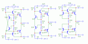
Found this on vegalab. The Akulinichev bias circuit appears to be a variant of the Hawksford error correction circuit.
Attachments
Thanks Egra!
Edit: not sure if this is the same thing as in the LMK amp..
Spreader in LMK (post #1) doesn't take feedback from the output, and the whole arrangement looks slightly different...
The 2nd example in your pic is more like it, but it's for BJTs. Will try to read about this Hawksford correction thing.
Edit: not sure if this is the same thing as in the LMK amp..
Spreader in LMK (post #1) doesn't take feedback from the output, and the whole arrangement looks slightly different...
The 2nd example in your pic is more like it, but it's for BJTs. Will try to read about this Hawksford correction thing.
Last edited:
It would be worth simulating whether there is a visible difference. If I remember correctly OldDIY said somewhere this is not only thermal compensation, but also a tricky class B bias circuit. It stabilizes the output current and dampens switching processes.
Last edited:
- Home
- Amplifiers
- Solid State
- Unusual amp from 1987