One advantage of an inverting configuration is that it is a stub of a mixing desk: simply duplicate C1/R12 input network n-times, and you get a clean n-input mixer, with low interaction between channels.
You can chose to multiply R12's value by n or keep them at 10K depending on input levels.
You can even make them variable.
Depending on the audio material and the way it was recorded, there might be cancellations at some frequencies, but that's kind of inevitable.
If the channels are mixed at the acoustic level (two speakers), cancellations will also occur, but they will probably be less sharp, and vary depending on the listening position.
With an electrical mixing, the cancellation will be completely independent from the listening position
Well that's predominantly 3rd harmonic on screen, so I'm unconvinced by the spice values...Because of the non-symetrical topology and the low feedback, low-order, even harmonics tend to be dominant.
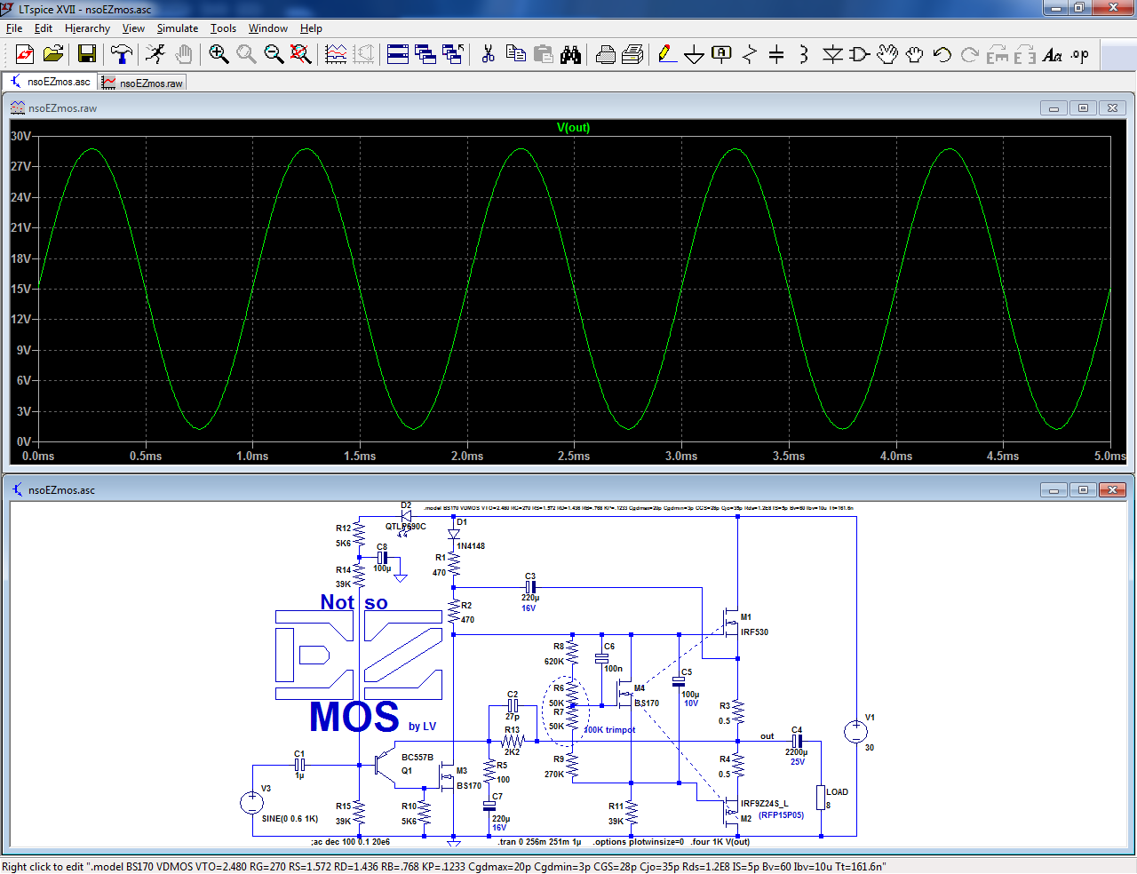
Here is the THD residue (0.15%) together with the output signal:
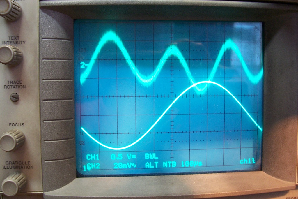
Well, neither am I, but that's the untampered reality, and to be honest the PMOS I used is different from the sim.
I tried to use a P-type that minimized the overall dist, because that's in fact what I prefer (except if the residue is something like Xover dist, which I hate).
This also explains why the measured THD is lower than the simmed one, a moderately rare instance.
Because complementarity does not actually exist for P or N MOS transistors, you are ~free to chose the ones that give you your preferred profile.
Another way of altering easily the profile is to make the source resistors different: it works in sim, and it will also work in reality (I didn't try it, but I am confident it will)
Is there a 'best practices' way to put both left and right channels from the source, with minimal cancellations, into an EZmos mono amp? ....
Two resistors.
There's no sensible alternative.
TWO resistors.
There's no sensible alternative.
Let's see ... ONE trimpot?
(a potentiometer with a knob would be a little bit arrogant in this case imho, but who knows...)
Consider for the input stage the ssm3k339 and use floating single supply as sublimed JLH1969
Yay!!! Single rail version of, Auto-center power!...and use floating single supply as sublimed JLH1969
If compatible with the amplifier, it should result in Reduced distortion at high output, especially in the case of music signal (which is variably asymmetric).
This little dynamic headroom enhancement is much better quality than a mild soft clipper could do. Also costs slightly more for split tank capacitance, and that's okay. But then the question is: Is there simply no change, or is it compatible with the amp (shows benefit)?
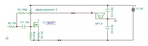
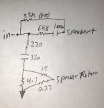
The simplest method, by far, is to revert to the classical, singleton input topology, in the Old Fashioned style.
Here is an implementation example, based on the most basic version of EZmos (it can be applied to the more evolved variants too):
It becomes self-centering for a wide supply range and C7 acts as an inverting input and can be tied to a current-sensing resistor to alter the output impedance.
Side benefits also include a lower THD level (0.025%) and a higher input impedance.
Attachments
I had to read the THD figure six times before it finally sank in how very low/good that is for a fet amp. Awesome. EasierMOS?...self-centering for a wide supply range and C7 acts as an inverting input and can be tied to a current-sensing resistor to alter the output impedance.
Side benefits also include a lower THD level (0.025%) and a higher input impedance.
But, the SMPS isn't doing any favors, and exactly 30v isn't convenient. I've had some difficulty/fails in estimating the voltage until after the fact. But, it is pretty clear that there should be a transformer.
Most common is 24vac and second is 30vac.
On weighting the factors, it comes up heavily in favor of the 30vac transformer as the power source (44vdc, or approximately 42vdc average if using).
This idea is tall and bumping into the spendy capacitor/tv room area, but didn't cross the line. So, it is still in scope. It seems a good plan that the biggest which is still in scope can 'fix' the voltage so that you'll have fixed target.
The question is, does it scale to 42vdc easily, and how does the THD estimate if auto-center power is also on the simulator schematic?
If that was a good idea, then indeed they are fixed targets.
The following question would be hookup points for partial current drive accessory, like 'x' marks the spot.
If that was all a 'go' then it is very low parts count for maximized audio functionality. It would be the first to formalize that at doable cost.
Thanks!Very cool design Elvee!
With this version, you are free to use whatever supply voltage you want (within reason, of course), if you use suitable semi's.But, the SMPS isn't doing any favors, and exactly 30v isn't convenient. I've had some difficulty/fails in estimating the voltage until after the fact. But, it is pretty clear that there should be a transformer.
Most common is 24vac and second is 30vac.
On weighting the factors, it comes up heavily in favor of the 30vac transformer as the power source (44vdc, or approximately 42vdc average if using).
This idea is tall and bumping into the spendy capacitor/tv room area, but didn't cross the line. So, it is still in scope. It seems a good plan that the biggest which is still in scope can 'fix' the voltage so that you'll have fixed target.
The question is, does it scale to 42vdc easily, and how does the THD estimate if auto-center power is also on the simulator schematic?
The OP power (and dissipated power) will be proportional to the squared supply voltage, as with any other amplifier.
The THD will remain in the same range, decreasing slightly with increasing voltage.
I will post an example, when I find some time.If that was a good idea, then indeed they are fixed targets.
The following question would be hookup points for partial current drive accessory, like 'x' marks the spot.
In principle, from ~10V to 45V, you don't need to change anything.If a span is permissible, 35vdc to 43vdc would be conveniently close to commonplace power supplies.
But, I was wondering if that would involve some value differences and/or a few higher wattage resistors?
If you go higher than 45V, the 470ohm resistors would need to be larger than 0.25W, and above 50V, the BS170 would need to be replaced by a device capable of dissipating more than 1W, but that's all that is required (minor adjustments in the Vgs multiplier and elsewhere might be beneficial)
Thanks! That's a lot of good news!
Attached: If I drew it right (not sure), the attachment has partial current drive.
I don't know how to hook that up correctly, together with auto center power (post32). They're both transparently mild; however, that combination of output functionality typically involves tubes/valves and a really flat wallet. So, it would be wonderful to do the job affordably solid state.
Attachments
Last edited:
- Status
- This old topic is closed. If you want to reopen this topic, contact a moderator using the "Report Post" button.
- Home
- Amplifiers
- Solid State
- Easy-MOS is a simplistic, efficient and evolutive all-MOS amplifier for beginners