So there is a little Gremlin sitting and waiting in your amp, ready to attack once everything is ready for use.
Hans
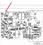
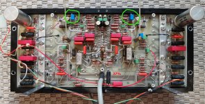
Hans, please tell me what regulates the tuning resistor on the ac 8.5 R60 Board highlighted with an arrow in the photo. And another question, 23.5 in the photo shows the voltage between the gold studs 83volt. And in 27.5 should be 65.2 volts?
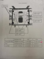
The last photo is taken from the service manual ml 27.
Attachments
Last edited:
The last photo is taken from the service manual ml 27.
Interesting insight, so they don't expect their service folks to remove the heatsink if they can help it

So there is a little Gremlin sitting and waiting in your amp, ready to attack once everything is ready for use.
Had it at the dealer, of course the Gremlin didn't show itself there. But I believe them. It was the most expensive adjustment of bias ever. A bit like owning an Italian sports car, but still cheaper. The upside is - it forces me to learn things, which is good
BR
Had it at the dealer, of course the Gremlin didn't show itself there. But I believe them. It was the most expensive adjustment of bias ever. A bit like owning an Italian sports car, but still cheaper. The upside is - it forces me to learn things, which is good
BR
Have you measured the capacitance of 1900uf 150v capacitors? How much do you have on 120 Hz?
I have 1720-1750. Esr 0. I'm thinking of changing them to new ones. I'm looking at Mallory or cornell Dubilier. What are your prices? I have a nippon ChemiCon dx. I wrote to Harman, telling us what can be replaced? They said that they are custom-made and they have a stock of new ones, they said you can try to buy them from the dealer...
Hans, please tell me what regulates the tuning resistor on the ac 8.5 R60 Board highlighted with an arrow in the photo. And another question, 23.5 in the photo shows the voltage between the gold studs 83volt. And in 27.5 should be 65.2 volts?
The last photo is taken from the service manual ml 27.
You adjust the DC output voltage of the inverting input amp.
So measure on P11 while turning the pot to set the offset voltage to zero volt.
Hans
You adjust the DC output voltage of the inverting input amp.
So measure on P11 while turning the pot to set the offset voltage to zero volt.
Hans
P11 relative to the earth? I have a constant 1mv in one channel and 5mv in the other I can measure at the output terminals?
Have you measured the capacitance of 1900uf 150v capacitors? How much do you have on 120 Hz?
They measured >1900uF. I have a set of spares that I picked up years ago. Don't know what they would cost from the dealer.
I think Harman orders a production run from time to time, perhaps if you bug them enough they'll sell you some when they are back in stock.
BR
Do you have a brown valve on the new 1900uf?They measured >1900uF. I have a set of spares that I picked up years ago. Don't know what they would cost from the dealer.
I think Harman orders a production run from time to time, perhaps if you bug them enough they'll sell you some when they are back in stock.
BR
Attachments
Last edited:
I just thought that the new 1900uf valve should be white. Unfortunately, I do not have a complete service manual �� there is only the beginning of the gle, the disassembly of the 27th is described and that's it.
just looked for new mellory for $ 60, so I thought to change them or something. I wonder how the replacement affects the sound do not know?
just looked for new mellory for $ 60, so I thought to change them or something. I wonder how the replacement affects the sound do not know?
So there is a little Gremlin sitting and waiting in your amp, ready to attack once everything is ready for use.
Hans
Hans, I'm having trouble setting up... Please help me.
P7 earth L1.678v. R1.7v
P6 earth L1.734v R1.77v
P6-P7 L3.45v. R3.46v
P11 earth L0.02mv R0.02mv
Constant output voltage R12.2mv L0.05mv
What should I do can you explain in detail? I configured P11. I set the quiescent current to 20mv what's next?
Hi Mark,
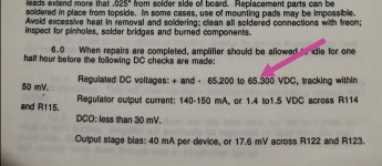
Almost everything seems O.K.
With 40mA per output transistor, this adds up to 160mA for 4 pcs.
Between WH13 and WH14, you should measure 160mA x 0.22R = 35mV.
The 20mV that you specified is that possibly between P16 and WH13 ?
Have you also set Vreg+ and Vreg- to be within 0.1V in absolute value?
When that's all done, there's normally nothing left to be adjusted.
I am a bit puzzled why LS out measures 12.2 mV, that's a bit on the high side.
With R3 you could bring this to zero volt if you like.
To achieve that, take out R3 and replace it by a pot ,somewhat larger than 100k.
Turn the pot until you have zero volt out. Take the pot out, measure it's value, and replace R3 with a fixed resistor of this measured value.
Hans
No, Hans, I didn't set up the current correctly. I have between wh13 and wh14 41mv. Now in 30 minutes I will reduce it to 35mv.Hi Mark,
Almost everything seems O.K.
With 40mA per output transistor, this adds up to 160mA for 4 pcs.
Between WH13 and WH14, you should measure 160mA x 0.22R = 35mV.
The 20mV that you specified is that possibly between P16 and WH13 ?
Have you also set Vreg+ and Vreg- to be within 0.1V in absolute value?
When that's all done, there's normally nothing left to be adjusted.
I am a bit puzzled why LS out measures 12.2 mV, that's a bit on the high side.
With R3 you could bring this to zero volt if you like.
To achieve that, take out R3 and replace it by a pot ,somewhat larger than 100k.
Turn the pot until you have zero volt out. Take the pot out, measure it's value, and replace R3 with a fixed resistor of this measured value.
Hans
Hans, please tell me how to configure vreg+ vreg-? I read that you need to output a voltage of + - 65 volts.
I will return to the 12.2 mv quiescent current later, first you need to alert everything.
Hans, I set up the quiescent current, but it was higher.
Hans but in the service manual to 27 it is written 65v and in the service manual 27.5 it is also written 65v.
At what points should I measure + -63v, I do not understand.
Yes, 12.3 mv in the other channel 0.02 mv
Hans but in the service manual to 27 it is written 65v and in the service manual 27.5 it is also written 65v.
At what points should I measure + -63v, I do not understand.
Yes, 12.3 mv in the other channel 0.02 mv
Last edited:
Oops, forgot the image.
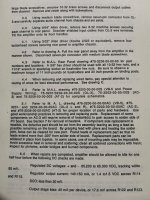
Hans, I attach a screenshot from 27.5 and from 27. And so de in post 190 you wrote that the current is worth putting 39.6 mV.
Hans that in the end will be correct? 35 mV or 39.6 mV 🙂
Attachments
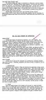
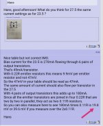
You are right, 65 Volt is the right value, sorry for the typo, good that you checked.
My earlier 180 mA was deducted from the ML23 with 45mA per transistor, but reading your manual, 40 mA was advised instead.
But it does make hardly a difference, so either 35mV or 39mV is O.K.
The +/- 65 volt should be measured at P1 and P4.
Hans
My earlier 180 mA was deducted from the ML23 with 45mA per transistor, but reading your manual, 40 mA was advised instead.
But it does make hardly a difference, so either 35mV or 39mV is O.K.
The +/- 65 volt should be measured at P1 and P4.
Hans
So there will be no effect on the sound from 35mv or 39mv? Then I'll leave 35mvYou are right, 65 Volt is the right value, sorry for the typo, good that you checked.
My earlier 180 mA was deducted from the ML23 with 45mA per transistor, but reading your manual, 40 mA was advised instead.
But it does make hardly a difference, so either 35mV or 39mV is O.K.
The +/- 65 volt should be measured at P1 and P4.
Hans
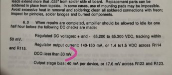
Vreg+ - 65v is set exactly ��.
I also read in the service manual that the constant voltage at the output terminals is up to 30mv within the tolerance, so I should not worry?
Or should there already be 0 mv at the output terminals at 27.5?
Attachments
Last edited:
- Home
- Amplifiers
- Solid State
- Mark Levinson No.27 amplifier,,,NEED HELP