This can only be caused by the soft start circuit.
Are the +Vreg and the -Vreg voltage within 0.1 Volt in absolute value after warm up ?
Hans
Are the +Vreg and the -Vreg voltage within 0.1 Volt in absolute value after warm up ?
Hans
Hans,
thank you for the hint.
I had set +-Vreg meticulously with my multimeter after warm up, so they are exact.
I measured them again, and they still are, but....
thank you for the hint.
I had set +-Vreg meticulously with my multimeter after warm up, so they are exact.
I measured them again, and they still are, but....
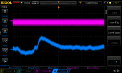
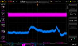
..looked at the voltages with my scope, and realized that Vmax and Vrms for -VReg is 0,2 higher than show by multimeter. So I looked at it in more detail:
upper is +VReg, lower is -VReg
So, apparently there is a problem with -VReg. Could this influence the soft start circuit?
Also, the lower graph seems to 'calm down' a bit with warm-up, which would explain why it tends to happen either right at switch-on or 5-20min into warm-up and then goes away.
Checked the other channel as well: both +- look like the upper graph, with +VReg *slightly* starting to ripple. So ok.
BR
PS: this ML has been at a dealer recently with the glitch description. They didn't hear the glitch while it was at the shop, which is possible, as it is really rare.
Attachments
Last edited:
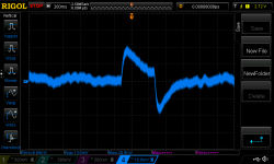
The noisy ML also had a problem with +-VReg, but, remember, it was noise (from C201, C202), but they don't have this ripple in the 100ms timescale like the 'working' ML above. I guess this explains the different symptoms.
PS: there is a little ripple in noisy ML right channel +VReg (where I have replaced the original spraque), but it's not triggering the soft start yet. Probably should fix this as well, good thing I have not disassembled it yet 😀 - want to fix all in one go. These old MLs are a piece of work.
So what could cause VReg to ripple like this? Defective C20, C21 or their bypass Cs?
BR
Last edited:
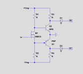
Below is the soft start circuit.
The Nmos is open at start up, so both transistors are conducting, forcing P6 and P7 to Gnd.
After a few seconds, the Nmos will become a short circuit because of a cap being charged slowly.
In that case both transistors will switch off, thereby releasing P6 and P7.
HOWEVER, suppose +Vreg is 1 volt lower as -Vreg.
Then the voltage on the Nmos through R1 and R2 will become -0.5Volt, thereby opening Q1 the PNP, so P7 will be forced to shut down while P6 will continue to operate.
This seems exactly what you describe.
Hans
Attachments
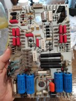
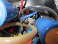
Start with inspecting with your scope the Pre Reg voltages on the two smaller large blue Caps that are feeding the regulators.The noisy ML also had a problem with +-VReg, but, remember, it was noise (from C201, C202), but they don't have this ripple in the 100ms timescale like the 'working' ML above. I guess this explains the different symptoms.
PS: there is a little ripple in noisy ML right channel +VReg (where I have replaced the original spraque), but it's not triggering the soft start yet. Probably should fix this as well, good thing I have not disassembled it yet 😀 - want to fix all in one go. These old MLs are a piece of work.
So what could cause VReg to ripple like this? Defective C20, C21 or their bypass Cs?
BR
They should show equal ripple.
I don't think C20 has anyting to do with this.
Hans
Good morning!
Hans, thanks for looking into this. The model for the soft clipping is incredibly helpful.
I set everything up so that I see what happens exactly to +- VReg when the glitch happens and Neg_Driveline goes flat, and what ripple at the blue VReg supply caps looks like.
Accidentally, the amp has been left switch on over night, so this morning VReg looks absolutely peachy (perhaps the caps have reformed), so I can't reproduce the glitch.
On a side note: had the impression it does not tend to glitch if turned upside down, perhaps because of the fluid distribution in the large caps, but that is wild speculation of course. Turned upside, I had measured the blue caps, and they looked fine.
Will report asap if I find out something new.
BR
Last edited:
Start with inspecting with your scope the Pre Reg voltages on the two smaller large blue Caps that are feeding the regulators.
They should show equal ripple.
I don't think C20 has anyting to do with this.
Hans
Hi, Hans! Thanks to you, ml 27.5 has been making me happy for a week now. Hans, do you think the twentieth series is a speed booster? I'm a little dissatisfied with the long bass, it's very well-developed, but a little slow. You don't think so about 20.6? maybe condencers are responsible for the bass speed?
It’s a bit difficult to answer your question, because a 20.6 could be quite problematic when still equiped with a teflon pcb for the amplifier board.
There has been an expensive revision with a later non teflon board which is O.k.
So be careful what to do.
About the sound, I can only give you my own opinion which is very positive, not only the bass but also the rest of the spectrum is very, very good.
Hans
There has been an expensive revision with a later non teflon board which is O.k.
So be careful what to do.
About the sound, I can only give you my own opinion which is very positive, not only the bass but also the rest of the spectrum is very, very good.
Hans
Could someone give me the size of the outlines of the lower board.
Looking at a picture it must be something like 13,7 x 31,8 cm.
Thanks in advance,
Hans
Looking at a picture it must be something like 13,7 x 31,8 cm.
Thanks in advance,
Hans
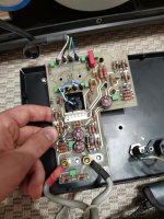
Can't measure exactly w/o disassembly, but AC-8 should be 14,5x32,33 cm (with the isolation sheet under AC-8, it should be 32,5).
BR
BR
Attachments
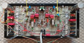
Hans, tell me what do the 470uf 10v capacitors on the boards xlr - rca. Do they affect the sound?
Those caps don't effect sound, they're there for overload protection.
But these caps don't have a good reputation, so replace them by 105C long life versions.
Hans
Can't measure exactly w/o disassembly, but AC-8 should be 14,5x32,33 cm (with the isolation sheet under AC-8, it should be 32,5).
BR
That's great, thank you.
I will include this information in my new design.
Two different base boards for resp the ML27 and the ML23, and one and and the same socketed amp board according to the most modern standards based on the ML23.5.
Hans
Accidentally, the amp has been left switch on over night, so this morning VReg looks absolutely peachy (perhaps the caps have reformed), so I can't reproduce the glitch.
Never happened again so far. I guess it will only happen after I closed to case and re-installed it into the rack.
BR
So there is a little Gremlin sitting and waiting in your amp, ready to attack once everything is ready for use. 😀 😀
Hans
Hans
- Home
- Amplifiers
- Solid State
- Mark Levinson No.27 amplifier,,,NEED HELP