Using a dB scale for harmonic amplitude with the fundamental at 0 would have been much easier for readers to understand, regardless of the merits of any other points being made here.
Then you didn't miss anything. I was just trying to help petr make things in dB scale, which he did not, so as to show him JLH is the much more distortive of the two despite the seemingly "clean" looking harmonic spetrum that petr appears to have been impressed with, yet mught not have realized what made it look clean -- the very dirty low order harmonics.
A speaker can work as a voltage generator by back-EMF but being a passive component, it is difficult to imagine it delivering voltage under negative impedance is difficult. Maybe you refer to Otala's [SIZE=+1]"[/SIZE][FONT=Times New Roman, serif][FONT=Arial, sans-serif]Peak Current Requirement of Commercial Loudspeaker Systems[/FONT][/FONT][SIZE=+1]" [/SIZE](JAES Volume 35 Issue 6 pp. 455-462; June 1987) ? It does not say that that the impedance of a speaker can drop to negative values.And of course, do not forget that the speaker system is not an 8 Ohm resistor, its impedance can significantly drop, up to negative values due to back-EMF - this is what
Last edited:
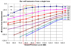
nattawa, low order harmonics (unlike higher harmonics) do not spoil the sound or irritate. On music, the 2nd harmonic is not heard up to 10%, the main thing is that it is below the harmonics generated by the ear. See graphThen you didn't miss anything. I was just trying to help petr make things in dB scale, which he did not, so as to show him JLH is the much more distortive of the two despite the seemingly "clean" looking harmonic spetrum that petr appears to have been impressed with, yet mught not have realized what made it look clean -- the very dirty low order harmonics.
A couple of notes on OOS amplifiers (for theory connoisseurs like fagos)
It is known that the phase of the signal turns earlier than the cutoff frequency of the amplifier (amplitude decay by 3 dB) earlier by about an order of magnitude (10 times). Therefore, in order for OOS to work correctly according to theory, the bandwidth of an amplifier with an open OOS loop must be wider than the audio range by at least an order of magnitude, i.e. from 2 Hz to 200 kHz. Only in this case will the loop gain in the audio range be in phase and the higher harmonics will not snowball.
Attachments
Last edited:
...low order harmonics (unlike higher harmonics) do not spoil the sound or irritate. On music, the 2nd harmonic is not heard up to 10%...
Not really. I taught myself what IMD sounds like in music reproduction, including for a 2nd order nonlinearity, the same nonlinearity that produces 2nd order harmonic distortion. I also listen at low SPL where distortion is not masked by loudness. Its not hard to hear, most people just don't know that's what it is that they are hearing, they don't recognize it as being a distortion.
Markw4, I recently had strange experience where some artefacts could be hear at low volume but were much less noticeable when played louder. It was a class A amp so it couldn't have been crossover distortion. Standard measurements look alright.
Graininess in mass string passages or chorus is what I hear. What was your perception?
Graininess in mass string passages or chorus is what I hear. What was your perception?
Last edited:
chip_mk,
Don't know how to describe the effect I was talking about in words that would make sense to someone else.
However a question if I may, how do you know the amplifier was responsible for the artifact?
Regarding graininess in musical passages as you describe, sound like maybe it could be higher order IMD. IME it tends to be more easy to hear in those cases. I hate to say this because some people may complain, but if an FFT doesn't show nonlinearity to account for it and you know other amplifiers don't do it, then I would say maybe it could be what I would call a nonstationary distortion. In other words, an audible distortion that doesn't stay constant long enough to show up well in a relatively longer distortion measurement time frame.
Last edited:
negative feedback amplifier
Yes Igor I know that, but here to be used English nomenclature.😉
I wrote to you earlier that your amplifier without NFB just creates a static error, and does not"react instantly". The amplitude subsides in accordance with the output impedance and is not compensated by anything. Read about static and astatic systems, maybe you will understand all the same, although I do not really hope for it.And of course, do not forget that the speaker system is not an 8 Ohm resistor, its impedance can significantly drop, up to negative values due to back-EMF - this is what Graham wrote about. And here it is important that the amplifier does a good job with both reactive impedance and low impedance loads.
And here it is important that it reacts instantly and in phase with external influence, as amplifiers do without feedback.
If you understood the theory, you wouldn't write such nonsense.A couple of notes on OOS amplifiers (for theory connoisseurs like fagos)
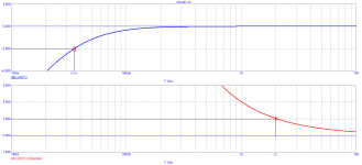
It is known that the phase of the signal turns earlier than the cutoff frequency of the amplifier (amplitude decay by 3 dB) earlier by about an order of magnitude (10 times). Therefore, in order for OOS to work correctly according to theory, the bandwidth of an amplifier with an open OOS loop must be wider than the audio range by at least an order of magnitude, i.e. from 2 Hz to 200 kHz. Only in this case will the loop gain in the audio range be in phase and the higher harmonics will not snowball.
The scale of the amplitude characteristic along the ordinate axis is logarithmic, and the scale of the phase frequency is linear. Therefore, visually, it seems that the phase begins to increase before the amplitude, but this is an illusion. Of course, unless you claim that the amplitude and phase characteristics for minimum-phase systems are uniquely unrelated...
Your second conclusion actually puts an end to most of the operational amplifiers produced. For example, AD823, AD797, LME49860 and the like. A bold statement that nevertheless requires a little more proof than just an axiomatic statement.
However, most of your axiomatic statements are taken from advertising articles, under which you are trying to justify-this is not news.
chip_mk,
Don't know how to describe the effect I was talking about in words that would make sense to someone else.
However a question if I may, how do you know the amplifier was responsible for the artifact?
Regarding graininess in musical passages as you describe, sound like maybe it could be higher order IMD. IME it tends to be more easy to hear in those cases. I hate to say this because some people may complain, but if an FFT doesn't show nonlinearity to account for it and you know other amplifiers don't do it, then I would say maybe it could be what I would call a nonstationary distortion. In other words, an audible distortion that doesn't stay constant long enough to show up well in a relatively longer distortion measurement time frame.
Plus that lots of CDs and streamed files come with built-in distortion 😉
Jan
Отрицательная Обратная Связь - ООС - in translation OOS - overlooked my cant. Yes - NFBnegative feedback amplifier
However a question if I may, how do you know the amplifier was responsible for the artifact?
I played familiar tracks.
Your comment draw my attention, about IMD being noticable at low volume and becoming masked at high volume. Usualy, distortions get worse with the volume, do we now if masking can offset increased IMD?
According to the calculations given in the book by Jiri Dostal (1981), to obtain an amplitude error of no more than 0.01%, the amplifier's passband should be 71 times wider than the extreme frequency of the audio range.
Thus, from above it is necessary to have a cutoff frequency of the amplifier of 20 kHz * 71 = 1.4 MHz. Similar to bottom 20/71 = 0.28 Hz.
Knowing the required bandwidth from above, it is easy to calculate SR.
With such a bandwidth, we will automatically obtain the required signal transit time (time Propagation Delay).
Well, as for the cutoff frequency from below, experts set it along a square wave (meander) with a frequency of 20 Hz, the shelves should be horizontal. This condition is met by a phase shift of no more than 1 degree, which fully fits into the calculations of Jiri Dostal.
Judging by the figures that I gave, a tenfold reserve of bandwidth in both directions is clearly not enough. A stock is required at least 50 ... 70 times.
When these conditions are met, speed distortions and distortions associated with transient processes disappear and only nonlinear distortions introduced by the amplifier remain.
Attachments

chip_mk,
Seems like it would probably depend on the details. How much worse is the IMD getting, how much is the SPL at the listener position, etc.?
Seems like it would probably depend on the details. How much worse is the IMD getting, how much is the SPL at the listener position, etc.?
You clearly do not know how to read, or you have a bad understanding of the essence of what you read. All the parameters of Jiri Dostal were given regarding systems that need a minimum delay in signal transmission - positioning systems, position control. In such systems, the minimum delays between output and input are really important, so its calculations are worth applying there. In the case of audio technology, the requirements are reduced, since we do not listen to the input-output difference signal, but only the output. So you should re-read and think again.According to the calculations given in the book by Jiri Dostal (1981), to obtain an amplitude error of no more than 0.01%, the amplifier's passband should be 71 times wider than the extreme frequency of the audio range.
Thus, from above it is necessary to have a cutoff frequency of the amplifier of 20 kHz * 71 = 1.4 MHz. Similar to bottom 20/71 = 0.28 Hz.
Knowing the required bandwidth from above, it is easy to calculate SR.
With such a bandwidth, we will automatically obtain the required signal transit time (time Propagation Delay).
Well, as for the cutoff frequency from below, experts set it along a square wave (meander) with a frequency of 20 Hz, the shelves should be horizontal. This condition is met by a phase shift of no more than 1 degree, which fully fits into the calculations of Jiri Dostal.
Judging by the figures that I gave, a tenfold reserve of bandwidth in both directions is clearly not enough. A stock is required at least 50 ... 70 times.
When these conditions are met, speed distortions and distortions associated with transient processes disappear and only nonlinear distortions introduced by the amplifier remain.
If you make the lower limit of the range 0.28 Hz, then all the infrasonic components will come to the input and cause an increase in the distortion of your speaker system, which is not working so low. Similarly, with the upper limit-amplify all parasitic leads and submit them to twitter for no clear reason.
For comparison, at the cutoff frequency of the amplifying channel and the first order of decay of 200 kHz, the difference in the amplitudes of the frequencies of 1 kHz and 20 kHz is -0.04 dB or about 0.5%. Can you detect this amount of linear distortion with your ear? I don't think so. I agree with the authors of the book "Musical acoustics" Irina Aldoshina and Roy Pritts, who write that the differential auditory threshold (JND - just noticeable difference) in the most optimistic case is 0.5 dB. Usually higher depending on the frequency and intensity of the test signal. And this is on single-frequency testing, and not under masking conditions with real audio playback. As you can see, everything fits together.

Please name the experts who claim that the 20 Hz signal shelves should be smooth. You understand that such a statement should be supported by criteria for evaluating "evenness". For example, specify the relative difference between the beginning and end of the shelves, or something else...
+1Plus that lots of CDs and streamed files come with built-in distortion 😉
Jan
Couple of years ago, I bought a classical music recording after having read a shining review, only to find out that massed strings (violins) to my ear were terribly distorted at crescendi. I asked the reviewer whether he heard any distortions, and he replied that the recording sounded fine to him.
The recording was made Record of the Year by the Grammophone magazine for both musical and technical merits. I had a look at it in a DAW and found it clipped at more than one place. Compression also seemed to have been employed - by nature, a nonlinear process.
Regards,
Braca
That was exactly what I tried to describe earlier with the settlement prcoess vs THD... 😱maybe it could be what I would call a nonstationary distortion. In other words, an audible distortion that doesn't stay constant long enough to show up well in a relatively longer distortion measurement time frame.
- Home
- Amplifiers
- Solid State
- First cycle distortion - Graham, what is that?