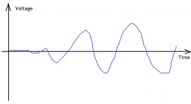
Let's leave the very 1st one. The 2nd period is already ok to use it as a 100% normal sine wave?
What if the 2nd period has a THD of 0.3%, the 3rd 0.2% and the 4th 0.01%?
According to that Fourier troublemaker, the right answer is: never. Once you are attempting to calculate the Fourier transform of the product of two functions (a step function and a sine) you will note that you'll have to wait an infinite time for the convolution product to converge.
So you need another (for example THD related) criteria to define the number of periods to wait until that THD value is reached (this is known as an "engineering" criteria). This means that if you tell me the THD threshold you want and the sine frequency/period I could be bothered to tell you the number of sine periods to wait until the THD drops under the specified value. If that's so important for you, of course, otherwise I do not support trolling around Fourier.
Last edited:
An engineer's maxim : an oscillator is an amplifier that ignores itself just as an amplifier is an oscillator that ignores itself.
The final target is of course to test the "settlement response" to the "random" changes in real life music.At this point you have to take into account how many cycles the brain needs to work out what is going on vs how often this occurs.
But we have to grab this "first-reaction-to-a-sudden-change aspect" somehow.
I (personally) am looking for a test which aims exactly this "spontaneity" aspect.
(Not to forget that in an amplifier there isn't just the musical input.
And so we have to be ready to handle some other "unmusical" control (error) signals as well.)
you'll have to wait an infinite time for the convolution product to converge
And what if the amplifier does some nasty things during the first few periods?
Just for the sake of me, what if the amplifier would do "random" output signal at the begining?
We don't want to know about it at all? We also cannot wait when we are listening to music.
Why should we wait exactly then when we perform a distrtion measurement?
Why we wait until it's completely settled to a continuous drive condition and then we check the distortion?
Or what kind of test could you advice which analyzes exactly this settlement process?
I'm not stuck to the step signal from zero at all. That's why I came up earlier with this attached
test signal (as maybe a compromise) which is 1 kHz sine starting gradually from 0 level.
What kind of similar test signal could you accept to check this aspect?
How fast should the amplitude grow to reach the nominal level?
And when we could start to check the distortion?
And why we have to wait at all? Isn't the very first reaction time section an extremely important factor?
Or is this test signal also unreal and misleading and useless?
Attachments
Cortez,
It might help us understand how to explain things if we knew more about how far you got in math. Any calculus, first or second year algebra, analytical geometry, etc. How far would you say?
It might help us understand how to explain things if we knew more about how far you got in math. Any calculus, first or second year algebra, analytical geometry, etc. How far would you say?
You mean that our ears probably don't hear the first few periods?You are constantly ignoring the temporal response of our hearing.
I learnt these at college of course, but wow, were my questions already that complex?Cortez,
It might help us understand how to explain things if we knew more about how far you got in math.
Any calculus, first or second year algebra, analytical geometry, etc. How far would you say?
I think you missed my point then. Why do you want to use "analytical geometry" at this point?
Common sense should be enough for now, I hope.
I don't want to calculate anything yet, just to clarify the basic idea, the layout, the method, etc...
BTW how could you help me on such quetions if you could use all these match "tools"?
And why the situation turned out that you should teach me something?
If my questions are so easy why you cant just simply reply (even without any math) to them?
I learnt these at college of course, but wow, were my questions already that complex?
You seem to missing the implications of the Fourier transform. Fourier transform - Wikipedia
That's what everyone keeps trying to explain to you. So far they have been trying to do that by giving examples that illustrate the mathematical relationship between time and frequency, in particular for the test waveforms that have been suggested in this thread.
I couldn't found any technical details. Can you please describe (just in a few bullet points) how a practical FT based TH distortion measurment works?You seem to missing the implications of the Fourier transform. Fourier transform - Wikipedia.
What's the algorythm? When does it start? How much time/period it samples, etc?
And would it be useful to measure my "incremental sine wave" signal as well?
BTW: some quotes from the wiki page you linked:
Wikipedia said:"Alternatives" section
This limits the usefulness of the Fourier transform for analyzing signals that are
localized in time, notably transients, or any signal of finite extent.
As alternatives to the Fourier transform, in time-frequency analysis, one uses
time-frequency transforms or time-frequency distributions to represent signals
in a form that has some time information and some frequency information –
by the uncertainty principle, there is a trade-off between these.
These can be generalizations of the Fourier transform, such as the
short-time Fourier transform or fractional Fourier transform,
or other functions to represent signals, as in wavelet transforms
and chirplet transforms, with the wavelet analog of the (continuous)
Fourier transform being the continuous wavelet transform.
"Signal processing" section
Even if a real signal is indeed transient, it has been found in
practice advisable to model a signal by a function (or, alternatively,
a stochastic process) which is stationary in the sense that its
characteristic properties are constant over all time.
The Fourier transform of such a function does not exist in the usual
sense, and it has been found more useful for the analysis of signals
to instead take the Fourier transform of its autocorrelation function.
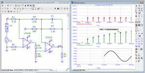
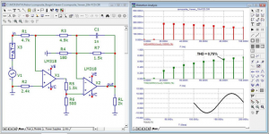
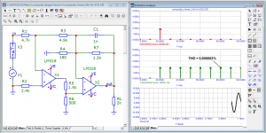
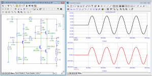
a question for experts in the Fourier transform. What is the difference between the first period of the generator and the first period at the output of the amplifier? I remember that the distortion of this amplifier in the steady state is < 0.000002%
Attachments
Lots of resources, for a few examples:
FFT.
Let’s Clear Up Some Things About FFT…
https://www.rationalacoustics.com/files/FFT_Fundamentals.pdf
FFT.
Let’s Clear Up Some Things About FFT…
https://www.rationalacoustics.com/files/FFT_Fundamentals.pdf
The answer is for those who still do not understand that the beginning of a sinusoid or a burst is a step signal. You do not analyze the sine in your pictures, but the sine + step with all the transition process from it. And the further away from the first period the analysis is made, the less there is a transient process and more of that sine, because the error decreases. For the same reason, all synthetic tests with bursts produce transients that are visible in transient analysis. Read the theory of linear chains on this subject, if the illustrations Jiri Dostal for you are not very eloquent.a question for experts in the Fourier transform. What is the difference between the first period of the generator and the first period at the output of the amplifier? I remember that the distortion of this amplifier in the steady state is < 0.000002%
Of course, the time constant of the amplifier is inextricably linked to the dynamic characteristics estimated by the transition characteristic, but we do not listen to the amplifier in this mode. Come to your senses.

Source of the picture: Shchepetov-Fundamentals of designing devices and systems (in Russian in the original)
Thanks Mark they are good resources indeed! Specially the 3rd one.Lots of resources, for a few examples
I read them and it confirmed me that FFT is mainly for continuous signals.
Some quotes from the 3rd link:
This confirms that it's mainly for continuous signals.Most of the acoustical and electrical signals that we may wish to measure are signals that are continuous,
that is, they have a defined value for every possible instant in time.
This tells that it's basically an averaging kind of method grabing usually more than one frame.These modes allow the user to fine-tune the averaging depth depending
on the measurement task and input signals: higher averaging frame counts
provide a slower time response, with lower numbers better approximating
the instantaneous behavior of the signal.
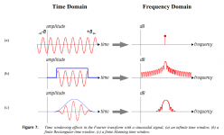
Windowing (see attachement #1) could help but also can cause trouble.The effect of this windowing operation on the frequency domain is obvious,
as the energy is dispersed into a single main lobe plus a number of side lobes
(called spectral leakage). The pattern of the side lobes is a function of the
rectangular window, and is primarily created by the abrupt discontinuity at
the edges of the window. The high relative level of these side lobes could
cause other important spectral information to be hidden, or masked.
However, if we apply a finite but gentle time windowing function,
as seen in Figure 7c, we can significantly reduce the level of the side
lobes by gradually tapering the waveform to zero at the ends.
A side effect of this operation causes the main lobe to increase in width,
which may also mask spectral details from nearby frequency components.
And wow, here (7c) is exactly "my" incremental kind of sine wave used as a test signal! 😀
So even a "fast" test takes 8-16 averages.Electrical measurements typically provide an inherently high signal-to-noise
ratio, so a short averaging time (8-16 averages or the fast response
characteristic) may be used for a more dynamic time response.
And on the other image (attachement #2) there is a step response but unfortunately they dont talk about it in details... 😡
Nor about the starting time of the test.
I'm not sure after this, is FFT then suitable to check for only 1 frame of sample as well?
Or it "is", just the resolution will be horrible and useless..?
Attachments

Were you under the impression that people have been saying a spectrum analyser tells you everything about a signal?
The reason fixed sine waves are usually used for FFT measurements is because the results are easy to interpret. One can calculate a 'figure of merit' to make simple comparisons between amplifiers.
To be more clear about the step function, its value is 0 until the time the step occurs, at that exact instant the step occurs its value abruptly changes to 1. It means if a continuous sine wave is multiplied by a step, the product of that multiplication will be the a sine wave that starts instantaneously when the step occurs. In that case there will be a frequency spectrum of the sine and a frequency spectrum of the step combined together.
Anyway, the argument that has been going on is that test signals with step functions in them produce a spray of frequencies many of which are not audio-band frequencies. The question in relation to that has been more or less to the effect, "what is the justification for testing an audio amplifier with very high frequency RF, or other non-audio frequency test signals?"
A closely related question might be, "The amplifier appears to be responding as it should to RF frequency components in a stepped test signal, but what bearing does that have on audio performance?"
In other words, someone is claiming using tests for an RF amplifier is needed for good audio amplifier performance. Why? What is the justification for the claim? What does RF have to do with audio?
If some kind of justification were to be to the effect that the RF might come in through the amplifier input connector, the what is the justification for not simply using a filter to adequately attenuate the RF before its gets into the amplifier? Why not do it that way? Why wouldn't that be a better way to design an audio amplifier?
Unfortunately, the responses to questions similar to the examples above seem to show a nearly complete lack of understanding of the issues being asked about.
Last edited:
I guess it's "just" a general concept that the better response/performancewhat is the justification for testing an audio amplifier with very
high frequency RF, or other non-audio frequency test signals?"
above the audio band can have benefits also at the audio band.
But I would turn the question around: could you give an example that if
someone designs an amplifier that can perform with a very high speed / small
signal propagation delay what kind of drawback it can have?
I mean why not to chase this aspect? Why is this approach such a problem?
I guess mainly because specially in a system with feedback there are inputswhat is the justification for not simply using a filter
to adequately attenuate the RF before its gets into the amplifier?
not just from the "official" input but from "everywhere" (PS, OPS, back EMF, etc)
so the more control speed margin we have the better the final result should be.
Another aspect (for me at least) regarding this whole FCD is this settlement aspect.
I'm not sure what was Grahams original idea: rather this step impulse kind of test or
the fact that the THD method usually waits for a long settlement time and even then
it takes a lot of frames and then averages the results. And that's why I asked:
what if the very first few periods are distorted the most? Which method correlates
better with random music: a method with a sudden (not necessarily a dirac style) signal
or a continuous one tested after waiting a few ms while the system calms down?
And I don't want to bring in the whole "memory distortion" kind of things but probably all designs
are differently "stateful" so it could be interesting to test a system with the same signal
but once right after a silent state and another time after a complex or high power section.
I think it's obvious that only one test can not give a 100% complete result.
As with a car there are a lot of aspects like speed, acceleration, maneuverability,
fuel consumption, noise, comfort, etc. In my mind it's the same with an amplifier too
and that's why it may be worth examining its response to different tests
and so even to a step signal, etc.
could you give an example that if
someone designs an amplifier that can perform with a very high speed / small
signal propagation delay what kind of drawback it can have?
Stability. An amplifier has many things it needs to do. One is to stay stable into whatever load you connect it to and the other is to fail safe, meaning it won't blow your speakers up when it oscillates itself to death. Quite a few high end amplifiers have failed in these two aspects.
One of the joys of DIY is you can, if you want balance your system according to your taste and you don't need a generic behemoth that will melt a nail if needed. If super fast floats your boat then there are designs out there to build. I've been listening to a Giovanni Stochino design for last couple of years. I can't claim any major sonic wonders for it, but it plays music.
Reading this thread is like reading a Facebook discussion where self proclaimed experts think they have a better grasp on things than published experts in the field and disregard the well established mathematical framework and formulas, predominantly in control theory, that are used in many fields and enabled us to put men on the moon, make the very device you read this on function, and are not up for discussion unless you want to argue 1+1=3, c’mon people the internet was supposed to make humanity smarter, not dumber!
Graham has repeatedly drawn attention to the fact that the amplifier has two inputs that are subject to external influences:
1) the input of the amplifier, which receives the useful signal and the feedback signal from the amplifier output;
2) the output of the amplifier - it is also the input on which the back-EMF of the speaker
acts Graham noted that amplifiers with a low delay in the high frequency region, such as the JLH-69 and some others, cope well with external influences.
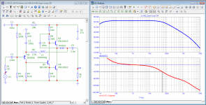
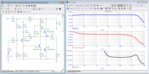
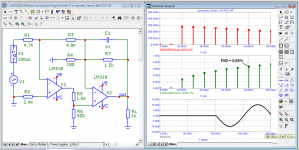
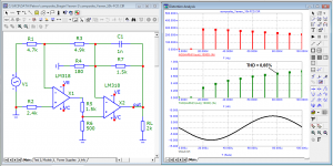
Let's compare the work of JLH-69 and Self-1 at a frequency of 20 kHz
The output impedance of the JLH-69 is more linear, and most importantly, its output (aka input) instantly reacts to the signal. These arguments Graham repeatedly cited both in this thread and on the site with the description of his amplifier The GEM.
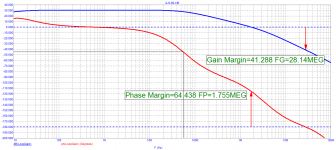
So what is responsible for proper operation of the amplifier? Look at the Bode diagram of the JLH-69 amplifier, the group delay at 20 kHz is 80 ns, the frequency of the first pole is 55 kHz - three times the audio range. In the area of HF Group Delay it is constant almost up to 500 kHz, therefore, there are no displacements of the HF harmonics of the signal affecting the timbre, localization of apparent sound sources, to the depth of the scene (sound image)
1) the input of the amplifier, which receives the useful signal and the feedback signal from the amplifier output;
2) the output of the amplifier - it is also the input on which the back-EMF of the speaker
acts Graham noted that amplifiers with a low delay in the high frequency region, such as the JLH-69 and some others, cope well with external influences.
Let's compare the work of JLH-69 and Self-1 at a frequency of 20 kHz
The output impedance of the JLH-69 is more linear, and most importantly, its output (aka input) instantly reacts to the signal. These arguments Graham repeatedly cited both in this thread and on the site with the description of his amplifier The GEM.
So what is responsible for proper operation of the amplifier? Look at the Bode diagram of the JLH-69 amplifier, the group delay at 20 kHz is 80 ns, the frequency of the first pole is 55 kHz - three times the audio range. In the area of HF Group Delay it is constant almost up to 500 kHz, therefore, there are no displacements of the HF harmonics of the signal affecting the timbre, localization of apparent sound sources, to the depth of the scene (sound image)
Attachments
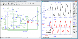
no theory will help you, so you don't understand how measurements take place in the simulatorThe answer is for those who still do not understand that the beginning of a sinusoid or a burst is a step signal. You do not analyze the sine in your pictures, but the sine + step with all the transition process from it. And the further away from the first period the analysis is made, the less there is a transient process and more of that sine, because the error decreases. For the same reason, all synthetic tests with bursts produce transients that are visible in transient analysis.
Attachments
- Home
- Amplifiers
- Solid State
- First cycle distortion - Graham, what is that?