I found something. Will come back in a few hours.@Hans:
The attached .asc file is very close to my real amp.
Differences and modifications which did not solve the problem
are marked in red in the pdf-File.
Remarks:
Power Supply is +-32V
I do not use a coupling cap at the input since my audio source has a low DC offset <1mV
Changing the BC5xx transistors to your suggested 2Nxxxx types
does not solve the problem.
@Max
I use 330R gate stoppers for the JFETs and 150R gate stoppers for the MOSFETs.
What NTC thermistor (value, brand) did you use in series with power.
At least the VAS is playing a big role in this.
Hans
Without looking at the PDF, I only tested Amnesis JFET.ascI found something. Will come back in a few hours.
At least the VAS is playing a big role in this.
Hans
To get the amp unconditionally stable, I had to do a few things:
1) I had to change R37 and R46 from 1K to 270Ohm. At the same time I could change R22 and R25 to 2k.
2) I inserted from the junction of R17/R36 a 27V zener with a 1N4148 in series to Gnd. And exactly the same zener and diode from Emitter Q6 to ground.
This way, the output stage can never be overloaded and/or start oscillating.
V(out) is now limited to +/- 25V pk-pk or 40 watt into 8 Ohm.
If you want a somewhat softer limiting, you can put resistors in serie.
You can now severely overload the input without any drama. The amp is really bomb proof.
3) I never understood the function of D1. It's better to use a bipolar for C7.
4) In the Circuit Diagram, C7 is 220, but this probably should be 220uF.
Hope this helps.
When you want me to go in the details of the PDF, let me know, but a BD139/BD140 pair for the predriver seems not to be a good idea.
Hans
Hello Hans,
thank you for your support.
I didn't populate the bootstrap caps C22/C27 so the sum R22/R43 and R25/R46 is in both cases around 2K.
It seems that it is not a problem of overloading the output stage
but a local problem of cascoding the output transistors. If replacing
the MOSFETs by a wire the problem does not occur.
I guess it is more a problem of bandwidth of the output stage (MOSFETs).
Decreasing the bandwidth/rise time of the input stage helps.
I already mentioned that the problem occurs only at a certain volume level. If increasing or decreasing the volume by 2dB the amp does not oscillate.
There is no need to look at the pdf-file.
Josi
thank you for your support.
I had to change R37 and R46 from 1K to 270Ohm. At the same time I could change R22 and R25 to 2k.
I didn't populate the bootstrap caps C22/C27 so the sum R22/R43 and R25/R46 is in both cases around 2K.
I checked that the limiting works but it didn't solve the problem.I inserted from the junction of R17/R36 a 27V zener with a 1N4148 in series to Gnd. And exactly the same zener and diode from Emitter Q6 to ground.
This way, the output stage can never be overloaded and/or start oscillating.
It seems that it is not a problem of overloading the output stage
but a local problem of cascoding the output transistors. If replacing
the MOSFETs by a wire the problem does not occur.
I guess it is more a problem of bandwidth of the output stage (MOSFETs).
Decreasing the bandwidth/rise time of the input stage helps.
I already mentioned that the problem occurs only at a certain volume level. If increasing or decreasing the volume by 2dB the amp does not oscillate.
There is no need to look at the pdf-file.
Josi
@Max
I use 330R gate stoppers for the JFETs and 150R gate stoppers for the MOSFETs.
What NTC thermistor (value, brand) did you use in series with power.
Any CL-60 (10R/5A) make will do: Amphenol, Vishay...etc. They are supposed to be self-healing. As per Mr. Pass' recommendation. In series with the "live" or, if you happen to have twin 110V primaries, in series, joining both.
")
Great work as usual. I will look at it when fully awaken from siesta.
I asume those elements with lines accross them are not connected (?).
*Do you have 5pF cap//FB Resistor?
*Do you have the 2K resistor (R51) that connects Mosfets' sources together?
*Output R (10 Ohm) is not there?
Try also Zobel after output R//L filter, for example at speakers' binding posts. If the problem only presents itself at power peaks, it coud be the case of injection of HF into ground from Zobel and passing it to sensitive (input) lines...though your competent design should make that possibility improbable...
Know that the output (driver-output) section works as a complete sub-circuit (or at least that is how I see it) so the bootstrapped output only makes visible a "local" (or global) resonance problem. If you don't succeed, maybe it is time to try those crazy R-C bypasses...
Good luck.
M.
PS: another clip.
YouTube
First slow movement, the fast movement starts at +/-4min 15s.
Last edited:
Why didn't you use the bootstrap caps c22/c27, they are vital, just as the 270Ohm / 2K mods. The caps don't have to be so large, 10uF is already enough.Hello Hans,
thank you for your support.
I didn't populate the bootstrap caps C22/C27 so the sum R22/R43 and R25/R46 is in both cases around 2K.
I checked that the limiting works but it didn't solve the problem.
It seems that it is not a problem of overloading the output stage
but a local problem of cascoding the output transistors. If replacing
the MOSFETs by a wire the problem does not occur.
I guess it is more a problem of bandwidth of the output stage (MOSFETs).
Decreasing the bandwidth/rise time of the input stage helps.
I already mentioned that the problem occurs only at a certain volume level. If increasing or decreasing the volume by 2dB the amp does not oscillate.
There is no need to look at the pdf-file.
Josi
Without you are in trouble.
Hans
Why didn't you use the bootstrap caps c22/c27, they are vital, just as the 270Ohm / 2K mods. The caps don't have to be so large, 10uF is already enough.
Without you are in trouble.
Hans
Indeed. All bootstrap caps (C16-C18; C22-C27) are needed for a proper QUAD bootstrap. Then tell me about dynamics.
I did try 10uF film caps (Hi Q Vishay) as bootstraps but found no significant sound difference, and they were more expensive and bigger...one can always bypass the electros with small film caps underside, if so one feels.
I think R output is also needed.
I would use only 65mA bias current at first for the tests.
What happens with the signal on the scope just prior to the oscillation? Do you see oscillation at the wave peaks?
If one peak shows tendency to oscillation (widening of the trace) then I would try the RC bypass (for example 20nF-50R if I remember correctly) from the corresponding bootstrapped driver's base to ground.
With the YT uploads, please neglect the HF distortion as it is mic induced. Focus on openness and dynamics.
Good luck.
M.

Oh Joy!
Today I found an upload from my Maestra with her, very young, singing the very demanding role of Lady Macbeth together the great Mario Sereni and conducted by Mario Rossi. Complete opera, BTW.
The technical quality of the recording is not that good, though. Considering it is from the RAI...
Anyway, a jewel of the golden era of Verdian singing.
YouTube
Good to hear you are enjoying music instead of listening to technicalities.Oh Joy!
Today I found an upload from my Maestra with her, very young, singing the very demanding role of Lady Macbeth together the great Mario Sereni and conducted by Mario Rossi. Complete opera, BTW.
The technical quality of the recording is not that good, though. Considering it is from the RAI...
Anyway, a jewel of the golden era of Verdian singing.
YouTube
At the end it’s the music that counts.
Hans
Indeed. But I try to do all things pertaining to the musical world. Maybe this year I will be able to upload some music clips.
I am still exploring this CLC supply both in high power and in low power circuits and I like it very much.
I am building my own coils, so it is not that expensive. With a power drill and a variac one can make a decent winding...
One aspect that I did not mention before for my TOKIN VFET single ended amp with LTMD input is that it was built with a donated transfomer which was too small for the task: the PS VDC was 60V instead of the expected 80V when passing 1A per channel, and regulated PS was 50V. The 25R loading resistor gave 25V left for the VFET...
After I inserted my DIY choke to for a CLC, the PS voltage jumped to 78VDC which went to 67VDC after the power regulators (I can reduce this fall perhaps) with 33.5VDC left for the VFETs now. Plus the already mentioned significantly reduced ripple.
I haven't yet listened to it on the big system. I am lazy to connect and disconnect equipment.
Cheers,
M.
Question.
How do you make a +/-42V supply with 24-0-24VAC transformer???
Answer: you make a CLC supply with a couple of DIY iron core chokes and you cross fingers. 

That is preciselly what I did with my JFET input Amnesis...and it worked!
Now I have increased power headroom almost for free.
First impressions are encouraging: good amplifier for those who suffer from tinitus Midbass (instruments' bodies) seem to have increased in energy.
My cheap meter says 2.4mH.
I can't figure out why this old technique, stolen from tube era, is not more extended amongst solid state warriors...worth a try if you ask me.
Apart, I have to share this video that my brother sent me. We both are proud members of generation X:
YouTube
Cheers,
M.
How do you make a +/-42V supply with 24-0-24VAC transformer???
Answer: you make a CLC supply with a couple of DIY iron core chokes and you cross fingers.
That is preciselly what I did with my JFET input Amnesis...and it worked!
Now I have increased power headroom almost for free.
First impressions are encouraging: good amplifier for those who suffer from tinitus
Midbass (instruments' bodies) seem to have increased in energy.My cheap meter says 2.4mH.
I can't figure out why this old technique, stolen from tube era, is not more extended amongst solid state warriors...worth a try if you ask me.
Apart, I have to share this video that my brother sent me. We both are proud members of generation X:
YouTube
Cheers,
M.
The last experiments were made to the power supplies. The amp has not been modified, but I received yesterday my N2222 BJTs for the VAS to be compared to MPSA18 (and BD139).
The CLC supply is trully amazing. The amp sounds now even more relaxed, fat and textured. Not like any solid-state amp that I know. I uploaded a clip: see my signature.
I am upgrading my very old crossover filters (AMT-1 monitor from the 70´s), something that should have done time ago : hard wiring, bypassing jumpers, pots, selectors, better binding posts and changing capacitors in the HF section, just the left one for the moment...it is a complex series-parallel XO with high value caps...
Now I am listening to some Brahms trios for piano.

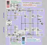
I attach the "official Amnesis power supply". Of course you can skip the charge-transfer part if you so wish. I will probably try that myself someday.
Only the lasts capacitor should be high quality: the previous could be normal heavy duty caps. Perhaps the improvement in sound comes only from increased voltage (32 to 42V) but I doubt it. I suspect the choke has something to do with it. Could it be related to "reactive currents" (apart the ripple effect) related? Those misterious reactive currents...
How did I made the DIY choke?
I took a couple of empty teflon tape formers (25mm internal diameter; 25mm wide +/-) that matched with an iron rod that I happenned to have.
Wind it with a Variac plus power drill machine to reach the desired turning speed...for the enamelled copper, I tried to match the secondary's width: 18G or 20G, I am nor sure...
For the SMPS a much smaller coil is needed between the extra caps. Mine are 0.3mH or so, if I remember correctly.
Cheers,
M.
The CLC supply is trully amazing. The amp sounds now even more relaxed, fat and textured. Not like any solid-state amp that I know. I uploaded a clip: see my signature.
I am upgrading my very old crossover filters (AMT-1 monitor from the 70´s), something that should have done time ago
: hard wiring, bypassing jumpers, pots, selectors, better binding posts and changing capacitors in the HF section, just the left one for the moment...it is a complex series-parallel XO with high value caps...Now I am listening to some Brahms trios for piano.
I attach the "official Amnesis power supply". Of course you can skip the charge-transfer part if you so wish. I will probably try that myself someday.
Only the lasts capacitor should be high quality: the previous could be normal heavy duty caps. Perhaps the improvement in sound comes only from increased voltage (32 to 42V) but I doubt it. I suspect the choke has something to do with it. Could it be related to "reactive currents" (apart the ripple effect) related? Those misterious reactive currents...
How did I made the DIY choke?
I took a couple of empty teflon tape formers (25mm internal diameter; 25mm wide +/-) that matched with an iron rod that I happenned to have.
Wind it with a Variac plus power drill machine to reach the desired turning speed...for the enamelled copper, I tried to match the secondary's width: 18G or 20G, I am nor sure...
For the SMPS a much smaller coil is needed between the extra caps. Mine are 0.3mH or so, if I remember correctly.
Cheers,
M.
Attachments
Last edited:
Hello
I've readed in the net, that using a vas transistor with very high ft , reduce the memory distortion.
Any ideas about that ?
Thank
Bye
Gaetan
Hi dear Gaetan.
Good question. Before our experts answer I will try by myself:In a sense yes, but Ft as I understand is a by-product of "speed" and that characteristic is related to capacitance of the unit (apart other parameters it seems) which is related to physical size. That is why we chose small BJT as VAS, cascoded to reduce further the (now non amplified) capacitance. I am sure there is more to it but I suspect this is the maiin reason.
BTW, about my linear CLC supply, as I said before, it privileges midrange and midbass in detriment of HF, so its presentation is "laid-back", meaning it will not appeal to all costumers or will not be good match with already "laid-back" systems. That characteristic is probably due to the size of the chokes that I used. I could try smaller ones in the future.
Fortunatelly, my SMPS with CLC extras, with little inductors does not present this feature: the sound became only much more clean and precise, without loosing punch.
Edit: my scope has a problem with horizontal sweep so I was not able to take a look at the outputs...I cannot dismantle it yet...
Cheers and glad you are around.
M.
Last edited:
I am back with the following comments.
Zobel network
Without zobel network the amplifier oscillates at 7..2 0MHz.
To stop oscillation a resistor < 20 ohms has to be connected to the
output. The inductivity should be well below 1uH.
A resistor of 10 ohms and a capacitor of 47nF mounted directly to the
PCB is a good choice.
Stability
The problem with my test track 'Royal March' (see post #577)
does only occur if driver and output are cascoded/bootstrapped.
The problem does not occur with
- Darlington version (output cascoded/bootstrapped, no driver cascode)
- cascoded/bootstrapped driver, output transistors connected directly
to power rails (no MOSFET)
@Hans
The presence/value of the bootstrapping caps (0...150uF) has only
a negligible effect on stabiltiy. The 270Ohm / 2K mods did not solve the problem.
In post #581 so mentioned
If I increase C10=100nF to 200nF in the VAS the stability of the
amp concerning my test track increases by a great amount. Increasing
additonally the Cap across the emitter resistors of the driver from
100n to 1-2uF the amp is stable.
I already mentioned that the problem does not occur for all versions if
input transistors Q3/Q5 (BC557C) are replaced by a p-JFET
(e.g. 2SJ103) which limits the bandwidth of the input stage so that the
rise time increases to 2us even without any input filter.
This option has the following advantages for me since
I use a DAC with very low offset and with passive volume control without output buffer:
- no input Cap required (sound coloration, high price, component volume)
- increased Input resistor (up to 100k)
- amp offset not dependent on source impedance
Listening Tests (JFET input with different output versions)
@Max
The amp sounds great in all versions
I am not so convinced of bootstrapping as you are.
At least in my audio chain / room acoustics the bootstrapping sounds a little pale and too fat in the mid bass region. It depends on the kind of music (my
focus is not classical music <20%).
So I will use no or only moderate caps in the driver / output section.
By inserting a switch for the VAS bootstrapping I can easily choose
between 2 different sounding amplifiers.
I compared the QUAD version to the Darlington version.
Both are sounding great. The Darlington version sounds less
voluminous / more detailed the QUAD more relaxed.
It needs more listening tests to decide which to use.
For people who want to design a less complex / more stable amp
I recoment the Darlinton version.
Power Supply
For many years I use an external CLC power supply (10.000uF-> 2mH
->22.0000uF) and I like it. Maybe I should reduce the inductivity.
AllBJT input
For the near future no tests are planned since I'm satisfied with the
more simpler JFET input.
Do you see any real advantages in sound with the more complex
AllBJT input
Component selection
What Caps / combinations do you prefer for
- bootstrapping driver/output
- bootstrapping CAP of VAS
- feedback Cap to GND
What resistors do you prefer for
- emitter resistors for the output transistors (0R22)
- 47R resistor in VAS
Did you find further components that are worth for experimenting.
Further listening impressions will follow.
Zobel network
Without zobel network the amplifier oscillates at 7..2 0MHz.
To stop oscillation a resistor < 20 ohms has to be connected to the
output. The inductivity should be well below 1uH.
A resistor of 10 ohms and a capacitor of 47nF mounted directly to the
PCB is a good choice.
Stability
The problem with my test track 'Royal March' (see post #577)
does only occur if driver and output are cascoded/bootstrapped.
The problem does not occur with
- Darlington version (output cascoded/bootstrapped, no driver cascode)
- cascoded/bootstrapped driver, output transistors connected directly
to power rails (no MOSFET)
@Hans
Why didn't you use the bootstrap caps c22/c27, they are vital, just as
the 270Ohm / 2K mods. The caps don't have to be so large, 10uF is
already enough. Without you are in trouble.
The presence/value of the bootstrapping caps (0...150uF) has only
a negligible effect on stabiltiy. The 270Ohm / 2K mods did not solve the problem.
In post #581 so mentioned
I found something. Will come back in a few hours.
At least the VAS is playing a big role in this.
If I increase C10=100nF to 200nF in the VAS the stability of the
amp concerning my test track increases by a great amount. Increasing
additonally the Cap across the emitter resistors of the driver from
100n to 1-2uF the amp is stable.
I already mentioned that the problem does not occur for all versions if
input transistors Q3/Q5 (BC557C) are replaced by a p-JFET
(e.g. 2SJ103) which limits the bandwidth of the input stage so that the
rise time increases to 2us even without any input filter.
This option has the following advantages for me since
I use a DAC with very low offset and with passive volume control without output buffer:
- no input Cap required (sound coloration, high price, component volume)
- increased Input resistor (up to 100k)
- amp offset not dependent on source impedance
Listening Tests (JFET input with different output versions)
@Max
The amp sounds great in all versions
I am not so convinced of bootstrapping as you are.
At least in my audio chain / room acoustics the bootstrapping sounds a little pale and too fat in the mid bass region. It depends on the kind of music (my
focus is not classical music <20%).
So I will use no or only moderate caps in the driver / output section.
By inserting a switch for the VAS bootstrapping I can easily choose
between 2 different sounding amplifiers.
I compared the QUAD version to the Darlington version.
Both are sounding great. The Darlington version sounds less
voluminous / more detailed the QUAD more relaxed.
It needs more listening tests to decide which to use.
For people who want to design a less complex / more stable amp
I recoment the Darlinton version.
Power Supply
For many years I use an external CLC power supply (10.000uF-> 2mH
->22.0000uF) and I like it. Maybe I should reduce the inductivity.
AllBJT input
For the near future no tests are planned since I'm satisfied with the
more simpler JFET input.
Do you see any real advantages in sound with the more complex
AllBJT input
Component selection
What Caps / combinations do you prefer for
- bootstrapping driver/output
- bootstrapping CAP of VAS
- feedback Cap to GND
What resistors do you prefer for
- emitter resistors for the output transistors (0R22)
- 47R resistor in VAS
Did you find further components that are worth for experimenting.
Further listening impressions will follow.
Big effort from your part, dear JOSI1. As always.
"You're doing a great job", as Trump says.
Thanks a lot for your support.
Enjoy.
M.
"You're doing a great job", as Trump says.
I am back with the following comments.
Zobel network
Without zobel network the amplifier oscillates at 7..2 0MHz.
To stop oscillation a resistor < 20 ohms has to be connected to the
output. The inductivity should be well below 1uH.
A resistor of 10 ohms and a capacitor of 47nF mounted directly to the
PCB is a good choice.
Apparently, our findings are comparable, but please post a diagram when you can, adding voltages. I have the zobel after the output R//L now. The two amps have being stable so far. I suspect that the CLC on SMPS is helping to the stability of my particular experimental amp...could be a faulty SMPS...
Stability
The problem with my test track 'Royal March' (see post #577)
does only occur if driver and output are cascoded/bootstrapped.
The problem does not occur with
- Darlington version (output cascoded/bootstrapped, no driver cascode)
- cascoded/bootstrapped driver, output transistors connected directly
to power rails (no MOSFET)
Sorry to hear. As I stated before, the beauty of our creation is that it combines the putative "LTMD" input and VAS sections, which are more or less resolved (more on this below), with whichever "driver+output section" one wishes to explore, from normal EF to more complex ones as cascoded driver+simple output, to very complex ones, like my desired cascoded-Sziklai output, which I will someday attempt.
I see the MOSFET cascodying element as a compromise, a useful compromise, since it resulted in a working amp with not that much complication, but my real hope is for the VFET cascode, which I will surely try ASAP. I recommend everybody get hold of some pairs while they last...
@Hans
The presence/value of the bootstrapping caps (0...150uF) has only
a negligible effect on stabiltiy. The 270Ohm / 2K mods did not solve the problem.
But they surely improve headroom and possibly the sense of dynamics? Didn't you notice it? Maybe my fertile imagination.
In post #581 so mentioned
If I increase C10=100nF to 200nF in the VAS the stability of the
amp concerning my test track increases by a great amount. Increasing
additonally the Cap across the emitter resistors of the driver from
100n to 1-2uF the amp is stable.
Sorry, the cap between drivers' emitter resistors?
C13 or C20, or am I looking to the wrong schematics?
Great that you solved it, though; one more tip to try when things go wrong.
I already mentioned that the problem does not occur for all versions if
input transistors Q3/Q5 (BC557C) are replaced by a p-JFET
(e.g. 2SJ103) which limits the bandwidth of the input stage so that the
rise time increases to 2us even without any input filter.
This option has the following advantages for me since
I use a DAC with very low offset and with passive volume control without output buffer:
- no input Cap required (sound coloration, high price, component volume)
- increased Input resistor (up to 100k)
- amp offset not dependent on source impedance
The input cap is not necessary at all. I added it to the .asc file after someone advised.
I have my TOKIN VFET amp like that, with n-JFETs. Now, if your voltages allow, try to cascode the JFET with another JFET, "inside" the CFP. For example 2SJ74 as Q3-Q5 and J103 cascodying them. For me, that mod opened-up the sound further.
Listening Tests (JFET input with different output versions)
@Max
The amp sounds great in all versions
I am not so convinced of bootstrapping as you are.
At least in my audio chain / room acoustics the bootstrapping sounds a little pale and too fat in the mid bass region. It depends on the kind of music (my
focus is not classical music <20%).
So I will use no or only moderate caps in the driver / output section.
By inserting a switch for the VAS bootstrapping I can easily choose
between 2 different sounding amplifiers.
I compared the QUAD version to the Darlington version.
Both are sounding great. The Darlington version sounds less
voluminous / more detailed the QUAD more relaxed.
It needs more listening tests to decide which to use.
We seem to agree on listening tests also. The QUAD with 5200/1943-MOSFET combination ("JFET input" which, remember, in my case means JFET as cascodying element), as I said before, is not what you would call perfectly transparent amp: it sounds fleshy and woody, with lots of muscle and perhaps some fat also.
Anyway, without my scope I cannot check if there is something wrong with it.
Strangely enough, this does not seem to be the case with my MJ15024/25-MOSFET combination.
For people who want to design a less complex / more stable amp
I recoment the Darlinton version.
Power Supply
For many years I use an external CLC power supply (10.000uF-> 2mH
->22.0000uF) and I like it. Maybe I should reduce the inductivity.
Great to hear. I am late to the party, then
AllBJT input
For the near future no tests are planned since I'm satisfied with the
more simpler JFET input.
Do you see any real advantages in sound with the more complex
AllBJT input
The ALLBJT input is not that complex, rather simple to build really, and the parts are easier to get and cheaper, which should be appealing to more costumers. And it sounds great to me.
For a real comparison I need to use exactly the same parts and power supply on both specimens, which, as I stated before, is not the case at the moment.
Component selection
What Caps / combinations do you prefer for
- bootstrapping driver/output
- bootstrapping CAP of VAS
- feedback Cap to GND
Please upload a diagram with your doubts so we can recommend or try and check
What resistors do you prefer for
- emitter resistors for the output transistors (0R22)
I am using really what I could get hold of, which are good quality Mundorf, if I recall well.
Mundorf M-resist 5W MOX | Hifi Collective
- 47R resistor in VAS
That part will be the subject of further experimentation after I get my N2222A BJTs installed and working. I have some DIY 43R here. If I detect significant improvement I will surely build 47R DIY honeycomb non-capacitive non-inductive resistors
Did you find further components that are worth for experimenting.
I already have my VFETs, two pairs of them. Who could ask for more...
Further listening impressions will follow.
How do you find the dynamics and depth for a tinny amp?
Thanks a lot for your support.
Enjoy.
M.
Last edited:
Once again, I was premature and exaggerated in my criticism for the (JFET input/5200/1943) QUAD: I totally forgot that the DAC was using a power cord made from industrial, double insulated 12AWG (or 10AWG?) common multi-strand copper wire.
I went to the other extreme now and installed instead a power cord made of solid core 12AWG OCC copper wire. At this point I must make clear that if the audience thinks that these elements cannot influence sound, I must declare diplomatically that I do not care about your opinion and that for me they do, especially with such a sensitive amp where you can feel the different "ambience" of the recording even before the music starts.
Well, the insertion of the new power cord totally changed the sound presentation to the other extreme so to say. I perceive flat response now, with extended highs, much transparency and detail: the excessive prominence of the mid-bass has disappeared. The sad part is that now some DDD CDs sound dry and sterile again. Forgiveness is suspended.
Time to try multi-stranded OCC copper wire PC.
There are also some PCs that mix solid core with multi-standed OCC copper wires.
Cheers,
M.
I went to the other extreme now and installed instead a power cord made of solid core 12AWG OCC copper wire. At this point I must make clear that if the audience thinks that these elements cannot influence sound, I must declare diplomatically that I do not care about your opinion
and that for me they do, especially with such a sensitive amp where you can feel the different "ambience" of the recording even before the music starts.Well, the insertion of the new power cord totally changed the sound presentation to the other extreme so to say. I perceive flat response now, with extended highs, much transparency and detail: the excessive prominence of the mid-bass has disappeared. The sad part is that now some DDD CDs sound dry and sterile again. Forgiveness is suspended.
Time to try multi-stranded OCC copper wire PC.
There are also some PCs that mix solid core with multi-standed OCC copper wires.
Cheers,
M.
Last edited:
Once again, I was premature and exaggerated in my criticism for the (JFET input/5200/1943) QUAD: I totally forgot that the DAC was using a power cord made from industrial, double insulated 12AWG (or 10AWG?) common multi-strand copper wire.
I went to the other extreme now and installed instead a power cord made of solid core 12AWG OCC copper wire. At this point I must make clear that if the audience thinks that these elements cannot influence sound, I must declare diplomatically that I do not care about your opinion
Well, the insertion of the new power cord totally changed the sound presentation to the other extreme so to say. I perceive flat response now, with extended highs, much transparency and detail: the excessive prominence of the mid-bass has disappeared. The sad part is that now some DDD CDs sound dry and sterile again. Forgiveness is suspended.
Time to try multi-stranded OCC copper wire PC.
There are also some PCs that mix solid core with multi-standed OCC copper wires.
Cheers,
M.
Hi Max,
Pangea offers mains cables with very good price/performance.
Hans
- Home
- Amplifiers
- Solid State
- The AMNESIS amp: a good amplifier, like a gentleman, has no memory.