For those who do not want to invest in JFETs at all, there is also the possibility of an "all-BJT input section", shown in attachment, inspired by the re-reading of Hephaïstos' patent, which includes much more complex organizations...the V1 voltage source can be set with different voltages to test the overall behavior and can be configured with different sub-circuits, including deriving it from the same (even a single) sub-circuit of the internal CFP cascode to save on parts.
M.
In fact, I think that I could replace the 4 (or 3 diodes) of the Vref for the "intra-CFP" cascoded BJT for a red LED, which would give the desired value and perhaps save some space.
I don't know if having only one CCS for the differential amp, instead of one per branch, would affect the behavior of the input section or its sound...

Having only one would simplify things.
I will post an example later.
M.
Hi Max,
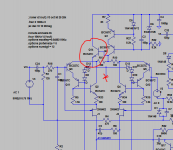
the circuit is looking a lot more stable now, something that concerned me
about the bjt cascode version, is the ground reference for Q12 and Q13.
I realise you might consider the modification below boot straped but the intention is to accuratly cascode Q3 & Q5. So terminology apart, the modification shown below simulates very well from distortion and step response.
And should make the input better able to handle larger signals.
I await to see your views on this.
Regards
Symon
Attachments
Hi Max,
the most critical parts of JFET based inputs is J1/J2 (2N5462) because they determine the DC operation points. When replacing 2N5462 e.g. with
2SJ103 and 2SJ74 the simulation does not work due to horrible operation points that are displayed when stopping the simulation.
Since the 2N5462 is hard to get (only SMD version MMBF5462 at Mouser) a suitable replacement should be found also for simulation.
Furthermore the production tolerances of the JFET have to considered when used in such a critical place.
Btw: What has to done to display the DC voltage in the simulation schematic (blue bold lettering).
Cheers
Hi Max,
the circuit is looking a lot more stable now, something that concerned me
about the bjt cascode version, is the ground reference for Q12 and Q13.
I realise you might consider the modification below boot straped but the intention is to accuratly cascode Q3 & Q5. So terminology apart, the modification shown below simulates very well from distortion and step response.
And should make the input better able to handle larger signals.
I await to see your views on this.
Regards
Symon
Wow! Good idea, dear Symon. I'll start experiments ASAP.
Actually, bootstrapping might sound better (positive feedback) but is potentially less stable.
the most critical parts of JFET based inputs is J1/J2 (2N5462) because they determine the DC operation points. When replacing 2N5462 e.g. with
2SJ103 and 2SJ74 the simulation does not work due to horrible operation points that are displayed when stopping the simulation.
Please download Hans Pollak's amnesis.lib
Since the 2N5462 is hard to get (only SMD version MMBF5462 at Mouser) a suitable replacement should be found also for simulation.
Furthermore the production tolerances of the JFET have to considered when used in such a critical place.
Btw: What has to done to display the DC voltage in the simulation schematic (blue bold lettering).
Right click on the node and choose "Place .op Data Label" (red 88) to view the voltages. But, how to reduce number of decimals???
The J1J2 problem: with ALLBJT version (now to be modded) you can set easily the voltage and operation points. J74 cannot tolerate high PS so it is only good for inside-FCP function, which BTW is sounding oh, so good.
My J103 work OK at least on 32V supplies and my batch set source V to -2.3V in both my amps.
Let me play a little.
Thanks guys!
M.
Last edited:
You got to -
-export your .lib to a .txt file.
-attach said .txt file .
Then , comment a " .include xxxx.txt " into your simulation.
Edit - better to keep OEM/custom models on a text file with a .include comment.
All LT's native ones will still be available. Copy-paste from the .txt to change a custom
transistor model.
Standard diodes , components .... LT will search the native .lib AND
.include for components.
Click and run !!
OS
Last edited:
You use OEM models. better ones below.
Just add .include KT-Cordell models.txt to your simulation.
Copy /paste " 2SC4793_A " from this text to replace your OEM " 2SC4793 "
you will see the glitches and oscillations that the oem's miss.
3X the info in the Cordell models versus the OEM's .
Simulation with the OEM models is unrealistic.
OS
Just add .include KT-Cordell models.txt to your simulation.
Copy /paste " 2SC4793_A " from this text to replace your OEM " 2SC4793 "
you will see the glitches and oscillations that the oem's miss.
3X the info in the Cordell models versus the OEM's .
Simulation with the OEM models is unrealistic.
OS
Attachments
You use OEM models. better ones below.
Just add .include KT-Cordell models.txt to your simulation.
Copy /paste " 2SC4793_A " from this text to replace your OEM " 2SC4793 "
you will see the glitches and oscillations that the oem's miss.
3X the info in the Cordell models versus the OEM's .
Simulation with the OEM models is unrealistic.
OS
Thanks!, dear Ostripper.
I have done before the .include xxx.txt but it did not work.
I will try again in another PC.
I have other questions, like when I test a new mod the square wave may look OK but the Bode may look worst. Which test will take precedence? And what other test to check stability? How can I display numerically stability margins?
I always forget to comment about the "Brilliant" Seal which is, well, brilliant
Years ago I bought a couple of collections: "Bach" complete works and "Russian Legends", a selection of live performances of Russian soloists from back in the old days. The cost per CD was (probably still is) around USD $1 and 1,5 as 100 CD packs, I don't quite remember the exact figure but still very convenient.
Cheers,
M.
Last edited:
Hi Max,I have other questions, like when I test a new mod the square wave may look OK but the Bode may look worst. Which test will take precedence? And what other test to check stability? How can I display numerically stability margins?
Cheers,
M.
There are two completely different testing modes within LTSpice, a small and a large signal simulation.
In a small signal modulation used for AC analysis, LTspice first finds the DC situation with Vin=0 Volt.
From thereon a simulation is made under the assumption that all DC settings remain the same, which is of course not the case in most situations.
Around this setting a very small amplitude simulation is made, no matter if you add an input signal of 1mV or of 100Volt, the outcome is always the same only shifted up and downwards.
No clipping or anything happens.
For that reason you have to be very careful in coming to conclusions with the Bode diagram, but its a very useful tool nevertheless.
A large signal model, the transient analysis, is doing exactly what you see, no tricks, no short cuts.
That's why a model may look stable with the Bode diagram, but heavily oscillating in the transient mode.
Hans
P.S.
According to Wiki:
A large signal model, on the other hand, takes into account the fact that the large signal actually affects the operating point, as well as that elements are non-linear and circuits can be limited by power supply values. A small signal model ignores simultaneous variations in the gain and supply values.
Last edited:
Hi Max,
There are two completely different testing modes within LTSpice, a small and a large signal simulation.
In a small signal modulation used for AC analysis, LTspice first finds the DC situation with Vin=0 Volt.
From thereon a simulation is made under the assumption that all DC settings remain the same, which is of course not the case in most situations.
Around this setting a very small amplitude simulation is made, no matter if you add an input signal of 1mV or of 100Volt, the outcome is always the same only shifted up and downwards.
No clipping or anything happens.
For that reason you have to be very careful in coming to conclusions with the Bode diagram, but its a very useful tool nevertheless.
A large signal model, the transient analysis, is doing exactly what you see, no tricks, no short cuts.
That's why a model may look stable with the Bode diagram, but heavily oscillating in the transient mode.
Hans
P.S.
According to Wiki:
A large signal model, on the other hand, takes into account the fact that the large signal actually affects the operating point, as well as that elements are non-linear and circuits can be limited by power supply values. A small signal model ignores simultaneous variations in the gain and supply values.
Dear Hans,
Thanks very much for the complete and useful explanation. I remember this was recently exposed in the "CFA, not-only..." thread. What distracted me is that some experiments show better square wave behavior (large signal model) than the predicted from Bode (small signal model) so that puzzled me.
My test amp with the last Miller compensation you proposed has been stable on the few hours I have been able to listen to it on the test system. It sounds nice but won't opine about it yet...
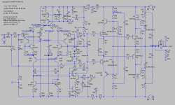
Here goes one possible implementation of the ALLBJT input amp. The square wave test is OK even with 20p Miller. The voltage references for the current sources can be set with any system for example initialy a pot to set the preferred operating points which give the best sound or numbers (Hephaïstos proposed very low Vce values for the input pair) and once established those, other less noisy devices, like diodes or LEDs, alone or in combination, can be set. This is the cheapest way we can go.
I know you guys can better my ideas, so I will wait for your critical revision of my humble efforts.
For now on I will trust more the brute force large signal square wave test.
Cheers,
M.
Attachments
Last edited:
Dear Max,
There are schools that propagate that the loop gain should be flat from 20Hz to 20Khz.
This is easy to achieve with the latest Bipolar/Fet version, because open loop gain is high enough.
When placing 500K in series with 100nF parallel to the Miller cap, the gain of the VAS will be linearized and reduced, but because of the feedback through this 500K, distortion will even drop.
In the images below you see the Loop gain in blue and overall gain in red.
Left image is as-is. The low frequency drop in loop gain is because of the used Bootstrap.
Hans
Dear Hans
I am sorry to say that the "linearized VAS" trick as tested on my "cascoded with BJT-CFP input" (39pF Miller) will not be part of the official recommendation. Maybe when 20pF arrive I will change opinion...
It surelly has an obvious effect on sound. The music became more ethereal, more relaxed, with good openness. Some sounds that were mere ghosts became more intelligible. Unfortunatelly, there was a significant drawback in one of the salient features of the Amnesis: loss of dynamic impact. The violence was lost. The concentrated energy of the plucking and of the smashing was not there, a mere facsimile, a cupon, a sophistication. No emotional transmision. As I have talked before, this may have to do with a smearing of the sound energy in the time domain which perturbs the "sound envelope" and precludes the brain to perceive the information as real sound from real instruments...in parallel there was a lost in mid-bass energy, which may or may not be cause or consequence of the former...as usually heavy on the bass amps sound to me "slower" and this is not the case here.
I had not the need to try the "47pF-100R" between Drains trick though it seems to help stability. Both tricks will remain as optional for experimentation.
The good part is that now my amp is running with 39pF Miller as is so far stable.
I probably wouldn't dare to try that before your advice.
Thanks again guys,
M.
PS: I may some day in the future try the ALLBJT input but summer finally arrived here so I cannot promise anything.
Attachments
Last edited:
Dear Hans
I am sorry to say that the "linearized VAS" trick as tested on my "cascoded with BJT-CFP input" (39pF Miller) will not be part of the official recommendation. Maybe when 20pF arrive I will change opinion...
It surelly has an obvious effect on sound. The music became more ethereal, more relaxed, with good openness. Some sounds that were mere ghosts became more intelligible. Unfortunatelly, there was a significant drawback in one of the salient features of the Amnesis: loss of dynamic impact. The violence was lost. The concentrated energy of the plucking and of the smashing was not there, a mere facsimile, a cupon, a sophistication. No emotional transmision. As I have talked before, this may have to do with a smearing of the sound energy in the time domain which perturbs the "sound envelope" and precludes the brain to perceive the information as real sound from real instruments...in parallel there was a lost in mid-bass energy, which may or may not be cause or consequence of the former...as usually heavy on the bass amps sound to me "slower" and this is not the case here.
I had not the need to try the "47pF-100R" between Drains trick though it seems to help stability. Both tricks will remain as optional for experimentation.
The good part is that now my amp is running with 39pF Miller as is so far stable.
I probably wouldn't dare to try that before your advice.
Thanks again guys,
M.
Dear Max,
Well it was worth a try, didn't it.
It just shows how sensible ears are for things you can't measure.
Didn't Einstein once said: What can be measured doesn't count and what counts can't be measured.
On the other hand, be careful in coming to conclusions too fast.
Let a change settle for at least a few days while playing permanently in the background at (very) a low level, it really can make a difference although it may seem a bit silly at first sight!
And looking for the holy grail, which you definitely do, you could also try 1Meg and 2 Meg resistors instead of 500K.
Bass and attack response are important, but they should never be larger than life.
For me most important are how well one can discriminate 3 dimensional positions of instruments within a orchestra and even more difficult, to hear articulation of voices in a choir.
The Mattheus Passion is one of my favourites for that.
But also LP's from the fifties with Ella and Louis can be reproduced breathtakingly realistic.
That was my small step aside for today, now back again to technicalities.
Hans
Yes, indeed. I couldn't agree more on your thoughts on the matter.
Depending on my mood, I am often inclined to the unsettling "Johannes Passion".
About burning-in...I always give at least two days (not complete) of mod evaluation. People that do not sense difference are adviced to follow another hobby.
I may try Symon's last idea about a activelly bootstrapped BJT-CFP input this weekend. As we now, perception does not always like the better technical answers...
Cheers,
M.
Hi Max,
the circuit is looking a lot more stable now, something that concerned me
about the bjt cascode version, is the ground reference for Q12 and Q13.
I realise you might consider the modification below boot straped but the intention is to accuratly cascode Q3 & Q5. So terminology apart, the modification shown below simulates very well from distortion and step response.
And should make the input better able to handle larger signals.
I await to see your views on this.
Regards
Symon
Dear Symon, guys,
Yesterday I found the time to perform your clever bootstrapping idea. It is really a fast an easy mod.
The effect on sound was totally unexpected: while the mid-bass and dynamics are comparable with the previous standard, the sound presentation became very laid-back, making the standard look very upfront and aggressive (the violence I talked about) by comparison; the detail and highs are there but recessed.
The voltages look OK and it is so far (few hours) stable. I don't know, maybe I need to reduce the CS resistor...
THD looks decent but I cannot make the square wave test to work...
Anyway, I don't know if I like it as it is now. Maybe I will perform my ALLBJT input mod sooner than expected.
Cheers,
M.
Last edited:
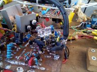
ALLBJT first channel done
With two yellow LEDs. I might replace the diode string with one (red) LED.
I saved two JFETs
They sound almost the same to me, though it is early.
This set the possibility to go to 60V supplies and parallel outputs for macho power.
I'll keep you updated.
M.
Edit: oops wrong file...
Edit2: the bootstrapping NPN can also be cascoded with base between Q1 and Q7...
Attachments
Last edited:
With two yellow LEDs. I might replace the diode string with one (red) LED.
Done. Red led instead of 3 rectifier diodes as Vref for the first bootstrap. Might not be perfect but is easy. Listening tests to follow.
Cheers,
M.
Attachments
Hi dear JOSI1,
Sorry. Too busy to post lately.
The ALLBJT INPUT bootstrapped amp (latest Symon's idea) is delivering the goods. It has the transparency and dynamics attributes which makes it an Amnesis amp. It should be considered the equivalent of the BOOTSTRAPPED JFET-CFP INPUT. The sound difference is subtle: the JFET is a bit more focused and images are denser; the BJT version is a bit more expansive and images are a bit softer. Without direct comparison there will be no complaint.
The red LED replaces with advantage the 3 diode string as Vref for the bootstrapped PNP's base at input. It should give -1,3V to ground for 32 to 44V supplies. With -2.1V to ground I got a simulated square wave output with 60V supplies, thought I have yet to try parallel outputs.
With two yellow LEDs I got -3.2V Vref from lowest bootstrapped PNP's base to ground. As I said before, experimentation with different values of Vref and different resistor values (of high quality) is encouraged for optimal function and sound.
LEDs sound better than diode rectifiers: more "continuous", more legatto sound, if you know what I mean...
As they carry low current, low power LEDs can be used in the input sub-circuit, with less real estate use...
I am very pleased.
I can't wait too hear your opinions on my (our) humble creation.
M.
PS: bootstrapping is the way to go IMHO. Making a stable amp with each stage bootstrapped, meaning with positive feedback, is a small miracle on itself, don't you think?
Attachments
Last edited:
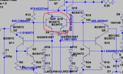
Hi Max,
Good to hear you are getting good results.
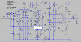
A slightly more elaborated version of the input circuit is shown below.
This should get closer to the JFET version, as each BJT cascode is now driven directly from the emitter signals, and not the common signal from the pair.
Anyway, something to think about and maybe try.
Regards,
Symon
Good to hear you are getting good results.
A slightly more elaborated version of the input circuit is shown below.
This should get closer to the JFET version, as each BJT cascode is now driven directly from the emitter signals, and not the common signal from the pair.
Anyway, something to think about and maybe try.
Regards,
Symon
Attachments
- Home
- Amplifiers
- Solid State
- The AMNESIS amp: a good amplifier, like a gentleman, has no memory.