Update schematics and layout
Although there are several items to be checked I want to post
an update of schematics and layout.
The update contains:
- 2 layer layout for shorter traces and increased width
- Combi layout CCS-VAS / Bootstrapped VAS
- Separate bootstrap for driver stage and output stage
(base/gate stoppers, 8 resistors 2W, caps to GND)
- Cascoded current mirror incl. degeneration resistors/ trim pot
for offset control
- feedback with 4 parallel resistors + cap
- split emitter resistors for driver stage with feedback cap
- driver stage / cascode on common heat sink (T-/U-profile)
transistors orientation base/gate -> collector/drain -> emitter/source
- RRDD string not included (yet)
Open issues
- stability problem
- decoupling caps
- transistors for VAS and CCS-VAS
Comments are welcome!
Attachments
Thank you very much, dear JOSI1.
I'll study them.
Sorry for not being active. I did simulations with lower valued resistors for drivers' emitters (lower THD and better margins) and lower bias current (10mA) for the VAS. That last one lowered THD but I got some strange curves that I suspect...
Anyway, I took a much needed rest, in the form of upgrading my DAC's output to a true LTMD output (first attempt was faulty) and now I am listening to that DAC (not perfect yet) and the TRIPLE BOOTSTRAP amp. The effect is additive.
What I am doing is making the differential output amplifier of the DAC a LTMD diffamp. That amp is fed through 4 OPA627 "buffers" from an AKA 4393 DAC chip. It now sounds dark and soft. For this little amp I discovered that it is necessary to match the active units, which are 2SK30A JFETs and BC560 for the compound CFP, cascoded.
Talking about input cascoded-CFP, I think this is more like a bootstraped/cascoded (so my amp is a QUAD BOOTSTRAP) because the JFET receives a sample of the AC signal, apart being tied to "ground"...what do you think?
The bootstrap is a form of positive feedback so maybe that is helping the perception of dynamics.
Cheers,
M.
Comments on first look at schematics:
D27: only recommended for CCS-VAS version.
R27: value depends on the BJT chosen for Vbe multiplier. Check Hagermann's paper.
I recommend putting pin sockets to support the majority R, for example E-C resistors for the cascodes; resistors for the CFP...etc.
RDRD can be "aerial", anyway.
About VAS BJT: keeping in mind that this is an experimental amplifier with a tendency for oscillation, I will commit heresy by recommending using at first a low beta T, like BD139.
Thanks.
M.
Last edited:
Hi Max
I've only been watching the development from a distance but one thing that might be worth a look was the use of the supply rails to feed the output/driver stage then to just use an RC filter to feed the front end - would a separate supply for the front end be worth the trouble?
I've only been watching the development from a distance but one thing that might be worth a look was the use of the supply rails to feed the output/driver stage then to just use an RC filter to feed the front end - would a separate supply for the front end be worth the trouble?
Hi dear James,
IMHO it is always best to use separate PS for the two sections, from a sound quality POV, but that would need separate TX or windings. For example, most SMPS carry independent (floating) secondary outputs, usually +/- 15 to 20V for 1A or less. That ones can be added to the main output and then fed through a high quality Vreg to the low poser section of the amps. For example, main output +/-44V, secondary +/-16V, summed +/-60V, then Vreg to say 50V. That way we can include the cascoded-cascoded-VAS without loss power headroom.
Cheers,
M.
Dear JOSI1,
It is really hard to check the two sided PCB. I hope your skill and your software did the best.
The most important, IMHO, is keeping the paths short for the cascode/bootstrap sub-circuits, to reduce parasitic inductance, loop area...etc. That way, the risk of oscillation from local loops is reduced.
Be aware that the compensation scheme is experimental, so one has to be prepared to go back to normal Miller compensation, or, to experiment with other forms of it.
I always forget to check if my relays have the exact pinout of yours.
Great job. I thank you very much.
Greetings,
M.
With my last experience modifying the differential output amplifier from my DAC to a LTMD circuit (cascoded-compound CFP input) I realized that I have to communicate a frequent observation. For some major upgrades or mods that I've done in the past months, while instantly noticing the improved dynamics and "sound's envelope", there is sometimes a "veil" very annoying. Usually the veil lifts in a couple of days, as I experienced with my DAC, and I blame the newly soldered JFETs and some BJTs and resistors...if the veil does not lift, further upgrades are considered.
Now I am in my fourth day and everything is sounding like real music, with impact, especially the solid attacks of piano high notes.
Patience, patience for the experimenter and seeker of light.
Dear JOSI1, have you considered a PCB for the "official charge-transfer supply"
I have some around because it is easy to DIY with thick copper plates, but that would help the hypothetical interested valiants...
I forgot to tell, once my strength is restored, I will try 15uF Poly caps as bootstrap for the drivers. Perhaps the difference in construction and shorter leads will kill oscillation. Perhaps Friday, the day of Freia or Venere.
Cheers,
M.
Report:
Original TRIPLE (QUAD) bootstrap amp is stable and sounding good to me.
DIY CCS-VAS double bootstrap amp is still presenting +/-80mv double freq. base oscillation.
I think the problem lies on the VAS-drivers area...
Removing C16 increased heavily the amplitude of the same oscillation. Increasing the value of C16 from 220n to 1u made no change.
Swapping 150uF electrolytics bootstrap capacitors for 15u film caps made no improvement.
Connecting C26 (100n from base of positive driver's cascode to ground) makes no change, but C27 (the negative one) is essential to avoid complete full power VHF oscillation and harm.
I have yet to try increasing base resistors for the drivers or adding BC capacitance for the same, with the original Miller compensation. Also, make both BJT of similar type.
Also, adding small capacitance between cascodes' bases...
Other ideas are welcome.
As you can see, experimental amps can be very frustrating sometimes.
This is not a good project for eternal beginners, like yours truly.
It is advised to have good experience, at least an oscilloscope and lots of resilience and "sang froid".
Cheers,
M.
PS: today, "parrillada" preparing fro the BIG fight.
Lets go Triple G!
Last edited:
Hi Max,
are you sure the problem is in the driver cascodes?
you could start by removing T17 and T18 so the driver isn't cascoded.
It's it still unstable then perhaps the problem is somewhere else.
do you still have C38 in circuit?. This capacitor can esasily cause HF stability problems as it increases the level of feedback at high freqencies, so at this stage best to remove if still present.
Regards,
Symon
Thank you, dear Symon, for your concern.
No. C38 was never fitted. Though the 4 resistors in parallel may have some capacitance which could affect FB.
Now I switched back to my highly regarded current-FB amp, which has very high slew-rate: no comparison to my beloved Amnesis, which has much lower slew-rate (slow amp) with regards to impact of the notes and dynamics; better sound's envelope. I also notice that Amnesis has more clarity and definition, though with certain software I still can hear some "grain". I have to fit the right complementary P-MOSFET.
A pity my knowledge and savoir faire is so limited...I guess it is this way that we learn.
Best wishes,
M.
Sorry for the silence.
I've been trying to de-bug it step by step. So far I think that:
The active CCS is not the problem.
Connecting the drivers directly (without cascodes) made oscillation worsen.
The parallel FB resistors are not the problem. Reducing FB resistor to 10k did nothing...
Different bypasses strategies did not improve it.
The type of bootstrap capacitor does not affect the oscillation.
Adding stopper resistors to input cascode JFETs does nothing to stop it...
I have a couple more tricks to try on the cascoded VAS, which is probably the culprit, and then I will be out of ideas. Probably will assemble everything, with the right P-MOSFET and pray to my local electric deity...I hope a professional PCB will have "negligible" parasitics and none of these will appear...
For now, I am catching up with my digital projects
A big mess...
Attachments
Last edited:
So, two SD card player+DACs upgraded and one new USB DAC built after I am stricking the project again.
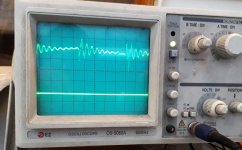
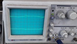
I attach a pic of the kind of oscillation I am having. Scale is 20mV and 1us. So now I have about 2MHz (the 80MHz is not there any more) and with elastic behavior of the resonant tank. Apparenty, there are many subcircuits that can resonate given the proper conditions. Now I have the output disconnected, to be safe, and the driver's cascodes without decoupling caps. I have the VAS cascode decoupled to ground instead of supply rail. Common Miller with 220pF.
I plan to alter the value of some resistances (and caps) here and there and reduce the path lengths as much as possible.
Anyway...today I plan to meet my mechanical man to build the monster heatsinks for the future two stage VFET amplifier with LTMD input section...that one won't oscillate.
Cheers,
M.
I am stricking the project again.I attach a pic of the kind of oscillation I am having. Scale is 20mV and 1us. So now I have about 2MHz (the 80MHz is not there any more) and with elastic behavior of the resonant tank. Apparenty, there are many subcircuits that can resonate given the proper conditions. Now I have the output disconnected, to be safe, and the driver's cascodes without decoupling caps. I have the VAS cascode decoupled to ground instead of supply rail. Common Miller with 220pF.
I plan to alter the value of some resistances (and caps) here and there and reduce the path lengths as much as possible.
Anyway...today I plan to meet my mechanical man to build the monster heatsinks for the future two stage VFET amplifier with LTMD input section...that one won't oscillate.
Cheers,
M.
Attachments
Hi Symon,
Basically, I am trying every single spot I think can have influence on the resonant circuit and change values and positions of Rs and Cs, and evaluate the behaviors...all I got is either that kind of curve (with the initial impulse bigger or gentler; with or without auto-controlled bursts of VHF oscillation, like in the present pic) or full blown VHF oscillation, for which reason I disconnected the output from power. The permutations and combination I tried are too many to describe...
Yesterday I tried, against my will, the simple, non-cascoded VAS and it did not make any difference whatsoever...nor did inverting the sequence of BJTs for the cascoded VAS. Increasing base R for the cascodes to 1K neither made any difference...
I also reduced Miller cap to 100p (standard for this type of amps) with no ill effect, which demonstrates, IMHO, that the problem is not global FB related but related to some local form of FB node(s)...
I'll make a drawing if today's attempt fails...
Thanks for your support.
M.
PS: this problem has exited my learning interest but I want to take it from the beginning so I am reading Faraday, Heaviside and J.J. Thomson.
Oscillation / Stability
Hi Max,
I don't know under which condition the oscillations occur.
I'd like to tell you some observations during my audio designs:
I had a permanent 20mV signal at the output of my Pass F5 Amp (no input signal) which was injected by the flourescent tube above my workplace. After switching off the tube the output was clean.
Usually I mount the PCB of an amp directly on the heat sink with a distance of
5-10mm. I could improve signal to noise and stability by adding a cap (10n-100n) from GND to the heat sink.
Hi
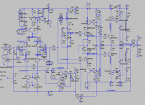
Regarding the schematic in post-159:
I believe it would be beneficial to add some electrolytics across each of D7,12 and then a 100n from end-to-end of this bipolar floating supply. In other projects using this type of the circuit, the electros filter the zener noise and the 100n eliminates noise at low signal levels.
Where the Cob of the output devices might be kept constant in this cascode, I feel like Symon that having it be high all the time would be problematic for the drive stage.
Like you, I have efficient speakers and my power needs are low. I dare say that if yours are 90dB-1W-1m then the signal you actually listen to is in the 10s or 100s of milliwatt level. This would mean that in real use the output is "hardly moving" (4Vpp, maybe - pretty darn loud at 87dB) and the Cob issue would not make itself known audibly.
Thank you guys for these very valuable advices. I will try them...I will try anything
that makes this project impregnable.
I have experienced that phenomenon of disturbance of the ether from the desk's light, dear Symon.
But I don't want to discourage the audience with my lack of expertise to solve this little real-life problem when simulations show it should work...I wish someone else tries this...
For the time being, I am licking my wounds with my LTMD TOKIN VFET amp.
I modified the input compound cascoded CFP to 2SK30 cascoded/bootstrapped with 2SK170, with BC560 as the counterpart. I am keeping resistors low: 1K and 330R.
Now the listening tests...
Thanks again,
M.
Attachments
OK. Some news.
I tried the recommended tricks.
A 100nF from ground to heatsink worked better.
A 10R+100nF (even 10nF) from driver's cascode zener circuit (from +8.2V to -8.2V nodes) worked better.
Better no mess with Mosfet (output) cascode circuit as the same added subcircuit caused full oscillation.
Electrolytics parallel zeners did not improve things. Remember I am concerned about oscillation, and not about THD.
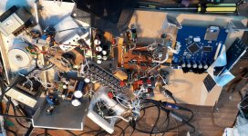
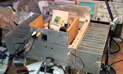
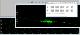
I attach some pics from the (reduced) oscillation I am having and the test circuit, and FFT, with 0.9V signal for 32V supply. The scope shows sort of a "pre-ringing", unlike the previous ones.
I suspect all this problem is related to my filthy test instalment...
Nevertheless, the amp did not go into full oscillation and I could listen some sweet music and even torture it. I connected two 16 Ohm speakers to the single channel I tested. Man, this is a superior sounding amp.
Thanks,
M.
I tried the recommended tricks.
A 100nF from ground to heatsink worked better.
A 10R+100nF (even 10nF) from driver's cascode zener circuit (from +8.2V to -8.2V nodes) worked better.
Better no mess with Mosfet (output) cascode circuit as the same added subcircuit caused full oscillation.
Electrolytics parallel zeners did not improve things. Remember I am concerned about oscillation, and not about THD.
I attach some pics from the (reduced) oscillation I am having and the test circuit, and FFT, with 0.9V signal for 32V supply. The scope shows sort of a "pre-ringing", unlike the previous ones.
I suspect all this problem is related to my filthy test instalment...
Nevertheless, the amp did not go into full oscillation and I could listen some sweet music and even torture it. I connected two 16 Ohm speakers to the single channel I tested. Man, this is a superior sounding amp.
Thanks,
M.
Attachments
Last edited:
I posted a short video from the, now two channel test amp, but obviously the mic from the phone does not do justice (no bass) to the test rig, with tablet as source (YT) and my cheap AIWA surround mini speakers transforned into transmision line...well one is still to upgrade to its final shape
I hope the dinamics are catched at least.
And, no, I did not manage to get rid of the episodic/periodic oscillation, but at least it does not go into full blown oscillation even at torture SPL.
YouTube
I hope you like it.
M.
I hope the dinamics are catched at least.
And, no, I did not manage to get rid of the episodic/periodic oscillation, but at least it does not go into full blown oscillation even at torture SPL.
YouTube
I hope you like it.
M.
- Home
- Amplifiers
- Solid State
- The AMNESIS amp: a good amplifier, like a gentleman, has no memory.