#7196@ Lower transistor with high frequency and large Hfe. The upper one is slower.
Try paar D1047.
I took the TIP41C and 2SC5198 out of the left side and replaced with TTC004 (genuine from Mouser) and D1047 (from LJM kit). I think that is a good combination. Very nice on quieter/more relaxing music including vocal, piano, acoustic guitar, strings. However for louder/denser mixes/music such as hard rock I still prefer the MA9S2, MX50x2 or L20.5.
I am wondering if I should explore current sources (as per JLH2003) and/or a few more volts to reduce distortion.
If anyone tries the TTC004 beware the reverse pinout relative to TIP41C.
Also the "F" marked TIP41C that came installed on these boards measure with hFE of 210 which is over twice the datasheet. So I have serious doubts about the authenticity of the stock transistors. Might have no relation to real TIP41C.
The Hfe of standard types of power transistor at a few mA test current is not going to be the same as at 1A or even 6A, as the TIP41 is specfied and Hfe typically falls to only ~20. Unfortunately, the little parts testers are only suitable for small-signal transistors. You have to get serious by using heatsinks, clamps, a regulated power supply and solid connectors to test power transistors for conformance.
Attachments
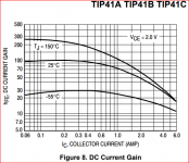
And those TIP devices I always considered as "low gain" types. At a useful current, of say 3A, the TIP41 has a minimum gain of 15. The TIP35 minimum gains are 25 at 1.5A and 10 at 15A, but if run in the range of 2-4A the gain is about the 20 mark and OK ish.
That is something to bear in mind, too.
That is something to bear in mind, too.
Increase the power of R6 and R7 (constant) and change the ratings as recommended JIH. Driver TIP41C (f).
Possibly shorter wires to transistors from PCB.
https://aliexpress.ru/item/32845029...9.1761510615.1601458988-1821516762.1598981413
Mosfet 250 uses cement 0.5 ohm and 220 ohm in the gate. Quiescent current 30-90mA. A voltage of 30-50V is recommended.
So if I were to choose between the Aiyima 1969M (without Source Resistors) or the Ghxamp 1969M (with 0.5 Ohm Source Resistors) would your recommendation be the Ghxamp?
AIYIMA 1Pair 1969M FET Bile Power Amplifier Board 25W+25W 1969 IRFP448 Tube Amplifier Home Sound Theater DIY Super 1875 3886 AMP|Amplifier| - AliExpress
Ghxamp 1969M FET Pre bile Amplifier Kits Board 1969 IRF250 Tube amplifier Board Bile Dual Channel UHC mos DC15 60V 1Pairs|tube amplifier board|amplifier boardtube amplifier - AliExpress
Attachments

Last edited:
Kozard- if you download the IRF510 datasheet (or other FET you might want to use) you will see that its drain current can double from 25C to 175C, so I'd use source resistors to give at least some degree of bias current control.
I take it that these "JLH" amplifiers with MOSFETS are operating in class AB. I'd be concerned about crossover distortion. I wouldn't buy any amp PCBs without checking published (verified) performance figures myself. Maybe someone has a link to such info.
I take it that these "JLH" amplifiers with MOSFETS are operating in class AB. I'd be concerned about crossover distortion. I wouldn't buy any amp PCBs without checking published (verified) performance figures myself. Maybe someone has a link to such info.
I take it that these "JLH" amplifiers with MOSFETS are operating in class AB. I'd be concerned about crossover distortion. I wouldn't buy any amp PCBs without checking published (verified) performance figures myself. Maybe someone has a link to such info.
I definitely agree. That is one of the main reasons I am posting here. Trying to get a suggested board/design to try based upon the experience of diyaudio members such as yourself.
Maybe I should just stick with the L7 (for MOSFET class AB) which is already soldered and awaiting final assembly. Perhaps the next step on my JLH exploration would be the JLH2003 boards pictured below. I have genuine 2N3055 (and actually MJ2955) which I bought decades ago for AN-484 amplifier projects.
The pictured JLH2003 boards have the current sources (and I would like to listen to the improvement from that) and I could assemble a polarity reversed version with PNP too. The only problem with those is that I don't have dual supplies in that voltage range. Only 50V dual supplies and 24V single supplies.
So I was wondering whether or not it makes any sense for me to make a little perf board current source with the two transistors and a trimmer to experiment with that aspect of the JLH2003 update on my existing mini1969 boards.
Does anyone have positive/negative experiences and/or recommendations with regards to the pictured JLH2003 boards? I think I should be able to figure out TO-3P D1047 mounting on those without too much trouble.
Attachments
Sounds interesting! Do post about it as you get on: it sounds like you're off on the right foot, so to speak.THe circuit I am currently exploring is not a zero feedback design. I also started with the premise that the device is more linear than a bipolar so chose class A and a bias current where the AC swing is pretty symmetrical so that it starts off like Susan's zero feedback amp - pretty linear before feedback is applied.
#7205 With resistors.
Check out Millwood here for about p.40 or #7191.
There are advantages and disadvantages over BJT.
Check out Millwood here for about p.40 or #7191.
There are advantages and disadvantages over BJT.
Last edited:
#7207@ Not Hood. Class A. 2003 without output capacitor better low frequencies. Unstable offset 0 at the output. We need the protection of the speakers.
Hot. Developed for the ESL-63 drive.
Hot. Developed for the ESL-63 drive.
The Hfe of standard types of power transistor at a few mA test current is not going to be the same as at 1A or even 6A, as the TIP41 is specfied and Hfe typically falls to only ~20. Unfortunately, the little parts testers are only suitable for small-signal transistors. You have to get serious by using heatsinks, clamps, a regulated power supply and solid connectors to test power transistors for conformance.
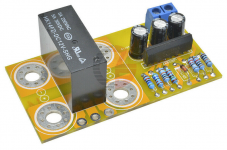
I am using a very simple setup of an 8 Ohm resistor (collector to supply) and 1k Ohm (base to supply) and adjusting the supply voltage until the collector current reaches 1.0 A (8.0V across the 8 Ohm). I have attached a photo.
It is a bit like the Elliott Transistor Tester except it is just one of the base resistors (I had 1k not 1.2k) and one collector resistor (I had 8 Ohms not 10 Ohms).
I have attached a photo with 8.05 mA into the base of a D1047 and 8.0 Volts across the 8 Ohm collector resistor (1.0 Amps). So (8.0V/8.0 Ohms)/(0.00805 mA) = 124. By the way, the M328 measures this transistor at 127 with Ie = 6.2 mA.
Do you see any problems/issues with this very simple setup?
Attachments

Last edited:
#7207@ Not Hood. Class A. 2003 without output capacitor better low frequencies. Unstable offset 0 at the output. We need the protection of the speakers.
Hot. Developed for the ESL-63 drive.
Is the standard uPC1237 speaker protection circuit sufficient/suitable?
Attachments
Edited- didn't see the direct path from meter to power supply. Should work OK but I caution again about measuring breakdown voltage. I would only test to spec.
Always start with the base resistor on highest, and check the collector current. If you see the current increasing, it means the device is getting hot, so keep the test duration short or use a bigger heatsink.
Always start with the base resistor on highest, and check the collector current. If you see the current increasing, it means the device is getting hot, so keep the test duration short or use a bigger heatsink.
Last edited:
Edited- didn't see the direct path from meter to power supply. Should work OK but I caution again about measuring breakdown voltage. I would only test to spec.
Always start with the base resistor on highest, and check the collector current. If you see the current increasing, it means the device is getting hot, so keep the test duration short or use a bigger heatsink.
Enclosed are photos of a slight modification which allows for Vce = 4.0V (or 5.0V if you want) for more direct comparison to datasheets. A 1k potentiometer is added in series with the 1k base resistor however the base current sense (voltmeter) is still just across the 1k.
This modification prevents Vce getting too low and thus gives a higher result.
Results for LJM Kit D1047 at Vce = 4.0V:
140 = (8.06V/8.0 Ohms)/(0.00719 A)
Results for Toshiba 2SC5200N (authorized distributor) at Vce = 4.0V:
127 = (8.09V/8.0 Ohms)/(0.00798 A)
I would prefer a 10 turn 2k potentiometer for ease of adjustment to 1A but I do not have one.
The goal is an accurate and comparable result that almost any DIYer could perform on their real or fake output transistors with equipment they are likely to already have.
Attachments


Last edited:
A very good question. The current sense and relay driver circuits of Chinese kits will typically work fine but first they have to be adjusted correctly to the output stage's SOA rating which is uh.... what exactly, now that I've tinkered with it? And how is this supposed to be carried out?Is the standard uPC1237 speaker protection circuit sufficient/suitable?
In situations where DIYs rely on kits without studying their function, I suspect they will have no clue whether their protection system works effectively or not. Also relevant is the fact that most DIY parts sellers and buyers choose the cheapest power relays possible because those designed specifically for audio tend to be very expensive.
The problem with virtually all mechanical relays, is breaking a DC fault current with only the spring force holding the contacts normally open. DC arcs are persistent which makes the contacts much harder to break apart than with AC currents, even to the point of welding them together, hence the lower DC current ratings.
For audio, always rate the DC protection relay by its DC ratings and for low to medium power amplifiers, make that at least 25V. If no DC rating, don't waste your money. Better still, build an optically isolated mosfet switch device that avoids the mechanical issues and is instantaneous in operation.
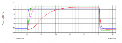
Some time ago I posted a comparison of the slewing rate of the JLH with various output transistors. With the recent interest in the MOS version, I have updated this comparison.
In the simulation results, the risign slew rate is shown for the following devices, in order of speed from slowest:
(1, red) 2N3055H
(2, purple) 2N3716
(3, orange) 2N3055 (epi)
(4, green) MJL3281A
(5, blue) MOSFET
Not convinced that the 2N3716 is really as good as a MJL.
So given that these models are "representative" rather than absolute, I'm pretty sure that the overall conclusion is right , in that the MOSFET wins, and if the circuit is adjusted so that the input stage does not cut off during the transient, this ought to be the best sounding one too.
(Note that the MOSFET design is a little limited in swing due to the higher gate voltage compared with a Vbe)
The MOSFET variant was operating in Class A and offers a (simulated) low distortion too.
All negative-going slews were similar.
I think all these posts on MOSFET variants of the 69 design should have its own thread.
Regarding the Millward design the circuit I simulated is virtually identical. Except, as noted in the following post (see OldDIY's ref) the simulations revealed that (a) you need gate stoppers and (b) an additional "stopper" of 1k in series with the input transistor base. And a compensation capacitor!
Attachments
Last edited:
I don't know if you have the models but is there any chance you could add the KEC D1047 and Toshiba 2SC5200N to the simulation?
I don't have models from the specific manufacturers for either. I've got a model for a 2SC5200, not sure of its origin at the moment, which shows a very similar result to the MJL3281a which is andy-c's version, but marginally faster and does not have the very slight overshoot, so appears "better", but slight differences in the model may or may not reflect actual devices.
Out of the thousands of models available, i certainly don't have time to evaluate the accuracy of each. Even validating one model can take a day or two of continuous measurements and refinements. Especially when it comes to temperature for example.
The people best placed to provide models are the manufacturers. They have the first-hand information about tolerances and averages, and ought to provide models for typical, and either worst case limits or something between, or ideally all five possibilities. Because some parameters are correlated either proportionally or inversely, and extreme models don't all have worst case parameters at the same time, necessarily.
I also think the SPICE model ought to be a maintained part of the datasheet, these days. UNfortunately at least one manufacturer has rather useless models, which does not help their sales I imagine.
Last edited:
I don't have models from the specific manufacturers for either. I've got a model for a 2SC5200, not sure of its origin at the moment, which shows a very similar result to the MJL3281a which is andy-c's version, but marginally faster and does not have the very slight overshoot, so appears "better", but slight differences in the model may or may not reflect actual devices.
Ok. Thank you. I asked about the 2SC5200N since it is a fairly readily available device from authorized distributors and has a good combination of price and performance. Right now it is my favorite device along with the D1047/B817 which arrived in many of my kits.
I am a bit shocked at how many fake devices I have uncovered after putting just a few days effort into testing them. From repairing a couple of SMPS I already knew that MOSFETs are terribly faked. As a result I am leaning towards sticking to just a couple of devices and sources I can trust. I want to try the 2SC6145 and 2SA2223 but the 2SC6145 are on back order and they are quite a bit pricer than the 2SC5200/2SA1943.
The D1047/B817 seem pretty good so far but I don't see them at any authorized distributors in the US. I might try to order them from overseas but so far I have had pretty bad luck with other part numbers. I test ordered TIP35C/TIP36C from a well rated seller and they turned out to be fake. [Badly fake, 10% of capacitance and 2x Vbe] I was not expecting that for the TIP series.
Farnell seem to sell the ST D1047 and ON Semi b187. Not sure why they've not got both manufacturers for both, but I'm guessing that ON Semi's will be on a similar line to the MJL1302, and perform similarly.
I think Farnell operate in the US perhaps under their Newark label.
I think Farnell operate in the US perhaps under their Newark label.
Unfortunately no 2SB817 at Newark. Previous had ON but no longer available. Only listed 2SD1047 is ST but out of stock.
Perhaps I should just be happy with 2SC5200/2SA1943. Especially if similar to D1047/B817. Then I can evaluate the 2SC6145 (when back in stock) and 2SA2223 as a possible "best" current-production part for my parts box.
Perhaps I should just be happy with 2SC5200/2SA1943. Especially if similar to D1047/B817. Then I can evaluate the 2SC6145 (when back in stock) and 2SA2223 as a possible "best" current-production part for my parts box.
- Home
- Amplifiers
- Solid State
- JLH 10 Watt class A amplifier