I might get a couple more of these very economical mini1969 boards to experiment with a PNP version and even a MOSFET version if possible. (Does anyone have a schematic of a MOSFET version using the mini1969 boards?)
One question I have is whether you see any issues with replacing each of the single NPN devices on the mini1969 with the attached sub-circuit of two paralleled NPN with emitter resistors (from the JLH2003 schematic). Assuming the correct heatsink and device matching is this ok? I can wire this easily with the extra two devices fixed to the heatsink.
One question I have is whether you see any issues with replacing each of the single NPN devices on the mini1969 with the attached sub-circuit of two paralleled NPN with emitter resistors (from the JLH2003 schematic). Assuming the correct heatsink and device matching is this ok? I can wire this easily with the extra two devices fixed to the heatsink.
Attachments
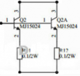
That depends. The MJ15024 is a "big beast" transistor, and can dump a lot of power. I've not looked at the mini1969 design as such, but if you plan to double the output current, remember to double the driver currents to suit.
Increase the power of R6 and R7 (constant) and change the ratings as recommended JIH. Driver TIP41C (f).
Possibly shorter wires to transistors from PCB.
https://aliexpress.ru/item/32845029...9.1761510615.1601458988-1821516762.1598981413
Mosfet 250 uses cement 0.5 ohm and 220 ohm in the gate. Quiescent current 30-90mA. A voltage of 30-50V is recommended.
Possibly shorter wires to transistors from PCB.
https://aliexpress.ru/item/32845029...9.1761510615.1601458988-1821516762.1598981413
Mosfet 250 uses cement 0.5 ohm and 220 ohm in the gate. Quiescent current 30-90mA. A voltage of 30-50V is recommended.
Last edited:
I wonder whether the JLH69 might benefit from a slew-rate limiting input filter.
As I have covered, probably in this thread a year or two ago (?) the design suffers slew rate limiting on the positive-going excursion (NPN output) when driven from a fast square wave. With TIP3055's or similar, it manages about 5MV/s. In a simulation where a 10kHz signal is also present, the 10kHz signal suffers about 4% distortion after subtracting the square wave output.
That can be reduced to about 0.8% with a 2.7k-560pF input filter. It can further be reduced using fast output transistors like the MJL3821A, which is why I generally prefer them to the older devices.
Many have claimed that normal signal material does not exceed the slew rate, so would not induce this transient induced distortion (or SID). I've been of the opinion that unless I could be sure, I try to avoid TID/SID so that it never occurs- at least with a bandwidth of 200kHz which is a factor of 10 higher than normal hearing.
I could imagine that a sudden transient on a record player pickup (mistracking for example) might cause a temporary glitch which is not in the recorded material, but might induce a TID/SID event. Whether that is audibly materially different from the glitch is another question.
This might explain why many suggest (as well as my own subjective impressions) that the JLH performs extremely well when handling single instruments, or voices, or limited collections but starts to become less clear when handling orchestral pieces with many instruments at once. (Not the only reason, ordinary intermodulation distortion can do this
too, which is why designs are trying to reach .001% instead of 0.1% THD).
The bandwidth of this filter is 100kHz. Perhaps some of you may want to compare with/without filters, if you think that TID/SID may be affecting your amp.
JLH + mosfet #421 Capacitor C2 reduced to 4.7 uF (shock).
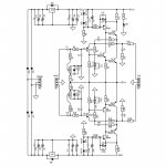
JLH 10 Watt class A amplifier
JLH 10 Watt class A amplifier
Last edited:
Increase the power of R6 and R7 (constant) and change the ratings as recommended JIH. Driver TIP41C (f).
Possibly shorter wires to transistors from PCB.
https://aliexpress.ru/item/32845029...9.1761510615.1601458988-1821516762.1598981413
Mosfet 250 uses cement 0.5 ohm and 220 ohm in the gate. Quiescent current 30-90mA. A voltage of 30-50V is recommended.
So 220 Ohm gate stopper and 0.5 Ohm source resistor. Correct?
I could clip the gate and source leads of the MOSFET and install the resistors between the PCB pads and the clipped MOSFET leads. (Keeping the PCB that I already have.)
That depends. The MJ15024 is a "big beast" transistor, and can dump a lot of power. I've not looked at the mini1969 design as such, but if you plan to double the output current, remember to double the driver currents to suit.
I meant the configuration of two outputs in place of each of my single 2SC5198 (or single TIP35C on the other channel). So that one channel would have two upper 2SC5198 and two lower 2SC5198.
I should have been more clear. The purpose is to make a 36V supply and something on the order of 1.5A safer/more reliable. (Using the 2SC5198 I have on hand.) So half or 0.75A/36V for each 2SC5198 worst case.
I was not planning on getting the MJ15024. So I am planning on doubling up the 2SC5198. Or really just starting to think about it. Or on my next order I might try a few FJA4313OTU (ON/Fairchild 2SC5242). Or just stick with the 2SC5200N (Toshiba) and order more to replace the ones used up fixing the MX50x2.
I also have a couple of 2SC6145 Sanken on backorder from Digikey. So maybe just one of those instead of two of the smaller devices? I hear that Sanken are more rugged/better SOA?
Last edited:
So 220 Ohm gate stopper and 0.5 Ohm source resistor. Correct?
Yes! Select V bias Q4 (Reduce R8 to 390-200 ohms in emitter Q2). Fast (+) supply voltage fuse. Reduce C2=4.7uf
https://aliexpress.ru/item/40000738...5.1761510615.1601458988-1821516762.1598981413
Yes! Select V bias Q4 (Reduce R8 to 390-200 ohms in emitter Q2). Fast (+) supply voltage fuse. Reduce C2=4.7uf
https://aliexpress.ru/item/40000738...5.1761510615.1601458988-1821516762.1598981413
Last edited:

Millwood - Former member of Dforum. Useful on 1969 mosfet.
http://bbs.hifidiy.net/thread-94645-6-1.html
http://bbs.hifidiy.net/thread-94645-6-1.html
Thanks, OldDIY. I have wondered about Mosfet versions but haven't been convinced that they were more than a novelty. In other words, an opportunity for designers to show their abilities but not necessarily having any benefits to performance.
I might build this again, since I have similar semis to Millwood's in parts boxes somewhere. What I'd like to do though, is buy some cheap PCBs only, so that I can run a set of comparisons with different builds at the same time and conditions.
Regarding Mosfet types, Many old TO220 types with high RDS that have been successfully used for audio, are now modified for lower switching losses, I understand. I suspect that just means the manufacturers are using a cheaper process but They are identified with an N suffix, like IRF530N.
No doubt, DIYs are simply buying these versions without question, but some professionals here have stated that this change isn't good. Anyone have a comment to add?
Millwood: @this amp isn't a low THD design (but certainly less than 1% in my experience) but it sounds great. kind of like Pass designs.@
@the BJT version is class A so that doesn't help. the mosfet version can work in class A or class B. In Class B, it should be quite efficient.
However, the MOSFET version loses a few voltage vs. the BJT version in terms of maximum output voltage swing, this causes the maximum output power to suffer.@
@when the mosfet version was introduced, someone actually tested it and showed a slew rate in excess of 25v/us.@
Advantages - speed, efficiency (class AB), power (30W / 8Ω)
Last edited:
I think MOSFETs can provide quite a high performance. My post about an input filter was based on some investigations following up previous work on slewing.
A developmental circuit I have shows that a test signal of 10kHz had 0.01% distortion in the presence of a fast square wave, without requiring an input filter. None of the transistors internally lock up or cut off during the transient. That was I think one of the key points about Otala's TIM distortion paper, even if his circuit was an unusual approach to solving it.
A developmental circuit I have shows that a test signal of 10kHz had 0.01% distortion in the presence of a fast square wave, without requiring an input filter. None of the transistors internally lock up or cut off during the transient. That was I think one of the key points about Otala's TIM distortion paper, even if his circuit was an unusual approach to solving it.
I think MOSFETs can provide quite a high performance.
In deep class-A, yes. Nelson Pass and Susan Parker have managed to do so.
In AB you need to leave them turned ON to get decent real world performance: otherwise the consequent loss of control and non-linear gate characteristics means weird and wonderful behaviour. This from personal experience with both "well designed" (hello Mr Tillbrook) and experimental (final year project) amplifiers which just loved to burst into ultrasonic song. Both measured wonderfully into 8ohm resistors. (Well, mine did only under certain specific conditions 😱)
A further problem for those playing along at home is that the spice models for mosfets have been found to be not very accurate (there's a few threads hereabouts - you'll have to do your own homework).
If (as is likely) the manufacturers are changing the underlying construction then all bets are off.
Last edited:
I was thinking of TTC004 as I was writing...so, as the newest driver types from Toshiba, why not give them a try with the proviso that they may be a bit too fast. If you can check this, look for signs of oscillation at supersonic frequencies up to 1 MHz.
Latest TIP41C/mini1969 progress. This morning I installed a genuine Toshiba TTC004 (from Mouser, authorized distributor) into the right channel which has genuine STM TIP35C outputs (from Mouser also, 2009 data codes and China so I think these are planar process?) I paired the TTC004 with the TIP35C because I am a bit afraid of the potential of oscillation with the TTC004 and 2SC5198.
Into the left side I installed a genuine STM TIP41C (from Mouser, ordered 2002 with 2001 date code, Morocco so I think these are mesa process?) The left channel has 2SC5198 outputs which measure reasonably for capacitance and BC diode at 9A so they might be genuine, but they are definitely not from an authorized distributor.
Bias current is now 1.2A at 24V.
Now I think the TTC004 & TIP35C side is improved over the TIP41C & 2SC5198 side. Both do well with female vocals, piano and strings. But now with more difficult/dense/loud mixes (such as hard rock) the TCC004 & TIP35C sounds like it has a fair bit less distortion. Relatively the TIP41C & 2SC5198 struggles and sounds harsher as if it has too much distortion.
Summary of other currently installed mods:
Power supply:
- (I am not suggesting that this is necessary or best, just had these series/values)
- 12000 uF 35V Nichicon LS capacitor (soldered to pins out output trans)
- 0.33 uF MKP capacitor (on bottom of board, left it there)
- 1000 uF 50V Nichicon VX capacitor (on bottom of board, left it there)
- 0.12 Ohm 3W Metal Film for Current Sense/Bias Sense
- NTC 10D-11 (Inrush)
Output capacitor:
- (I am not suggesting that this is necessary or best, just had these series/values)
- 10000 uF 50V Nover audio power supply filter capacitor (might not be genuine)
- 0.47 uF MKP capacitor (on bottom of board, left it there)
- 1000 uF 50V Nichicon VX capacitor (on bottom of board, left it there)
Input capacitor:
- Came with 1.5 uF box capacitor (likely MKP) (left it installed)
- 10 uF 50V Elna RE3 Audio (added on the bottom of the board)
Last edited:
Chinese sell kit ($15-20)...
Hmm, a 5 transistor JLH? I don't think you want to get involved with that design as there are a few HPA designs that follow the original JLH design and you wouldn't enjoy having to defend this particular variation unless you had compared it with one similar to the original, yourself.
Thanks for your comments Old DIY and Ian.
Yes, I found the Chinese kits sch.
JLH 1969 Class A Power Amplifier Audio Board Dual Channel Preamplifier Headphone Amplifier Single Ended Pre AMP| | - AliExpress
Attachments
In deep class-A, yes.
In AB you need to leave them turned ON to get decent real world performance: otherwise the consequent loss of control and non-linear gate characteristics means weird and wonderful behaviour.
A further problem for those playing along at home is that the spice models for mosfets have been found to be not very accurate (there's a few threads hereabouts - you'll have to do your own homework).
If (as is likely) the manufacturers are changing the underlying construction then all bets are off.
I've certainly blown a few MOSFETs up in power amps which have oscillated.
The circuit you referred to seems to be quite old. In the early days, people seem to be unaware of the vertical MOSFET having such a fast response that lead inductances became important and often MOSFET circuits oscillated for want of simple gate resistances to stabilise. And I'm pretty sure most of the early models out there don't include the lead inductances. MOdels from Siemens (INfineon/ IR) certainly do now.
However, the inductances can be included as parasitic components.
The physics of the vertical MOSFET are quite different, and if newer devices use trench drains, the resistances need quite detailed simulation to try to represent 2D device analytically. I have not looked into this, so perhaps I assumed too much that the models have caught up with reality given that the power FET has been around for 40 years now. But there again, I should have not been optimistic as the older SPICE models for JFETs and ordinary lateral MOSFETs (as used in IC's) still show errors and really, those old models need to be retired.
However, I'm not so sure about the lateral FETs that were popular at one time. They had a lower frequency response and while I tried Hitachi's early devices, it did not appear obviously better than bipolar designs of that era - the claim seemed to hinge more on a simpler circuit to achieve a respectable performance. But they may well have been less prone to oscillation as a result of the lower frequency response.
I am not convinced about leaving MOSFETs on. What may be occurring is that people forget that the gate charge can be very large. Just because there is a high DC resistance in the gate which can be 100 M or so, again, in early days, what was overlooked was that the gate needs a lot of charge to switch on. In fact, when I compared the net charge with a bipolar, it was not a lot different. Just a smaller current but at higher voltage. So this depends on the driver circuit as to how fast it can turn the device on - and off. So my view is that if the drivers are designed properly, the MOSFET can be controlled properly too. (Switch mode power supplies, for example, need drivers that can dump charge quickly).
I'd agree, though, if that wasn't taken into account, then keeping the device on would not need quite such a boost around the crossover region.
THe circuit I am currently exploring is not a zero feedback design. I also started with the premise that the device is more linear than a bipolar so chose class A and a bias current where the AC swing is pretty symmetrical so that it starts off like Susan's zero feedback amp - pretty linear before feedback is applied.
Last edited:
#7196@ Lower transistor with high frequency and large Hfe. The upper one is slower.
Try paar D1047.
Try paar D1047.
#7196@ Lower transistor with high frequency and large Hfe. The upper one is slower.
Try paar D1047.
Do you mean replace both output transistors with D1047?
- Home
- Amplifiers
- Solid State
- JLH 10 Watt class A amplifier