Manufacturers who produce only an NPN or PNP type but not both complementary power transistors, are unlikely to be supplying the audio market. There have been several other manufacturers in the S.E. Asia region who have been or still do produce just one type, mostly NPN and perhaps for industrial power supplies or similar large scale applications .
Which is a whole 'nother rabbit hole to disappear down: a JLH on steroids using a pair of such industrial-rated devices . A.K.A. How many class A watts can you get with just two transistors?There have been several other manufacturers in the S.E. Asia region who have been or still do produce just one type, mostly NPN and perhaps for industrial power supplies or similar large scale applications .
Yes, a complete p***ing contest but... 😀
Well, start with high power devices!
Once upon a time there was a company called RCA who produced a 300W transistor. I sometimes wondered about a 2N5575 for a high power JLH, but the frequency response was rather poor for audio. So never got any, even to try.
The MJ21194 would be a starting point today.😀
Once upon a time there was a company called RCA who produced a 300W transistor. I sometimes wondered about a 2N5575 for a high power JLH, but the frequency response was rather poor for audio. So never got any, even to try.
The MJ21194 would be a starting point today.😀
Yes, the MJ/MJL 21193/4 series are great semis for class A, though it's a pity they cost an arm and a leg (about ₤6 ea. in small quantities for Brits or US $7). It makes you think twice about experimenting with these when they represent such a high proportion of the electronic assembly costs.
Last edited:
A suggestion on cooling, FWIW. Use mica and white grease with these semis. The silicone rubber washers are fine for typical class AB but not up to serious class A heat with reliability. Good, dead flat and thin mica isn't a certainty nowadays so be careful who you buy from and get the thinnest you can afford or learn to properly split the stuff yourself.
Is 0.12mm good for Mica insulators for Class A JLH? (JLH2003?) Or is there better? I found "TOSAI TO-3PL 22*29*0.12mm Mica".
50/100pcs TOSAI TO-3PL 22*29*0.12mm Mica sheet Insulation sheet | eBay
I believe aluminium oxide insulators are the best, I use some thin ceramic washers ex ussr military stuff, quite good
It seems to be good quality, certainly better than some 0.4mm junk I've seen on the "the bay" and good enough for the application. I used the Aavid company's datasheet as a reference and their mica products seem to be in the 0.05-0.1mm range which is becoming thin, delicate and expensive at about US 50c per piece. The deal you have there looks to be a real bargain, assuming the average thickness is closer to 0.08 than 0.12mm.Is 0.12mm good for Mica insulators for Class A JLH? (JLH2003?) Or is there better? I found "TOSAI TO-3PL 22*29*0.12mm Mica".
I would hesitate to recommend beryllia insulators. Any chips could lead to the toxic dust you mentioned.
Alumina is, however, pretty good at 27 W/m/K. Compared with mica at 0.7. Traditional TO-3 mica washers with silicone gloop reckoned to be about 0.4K/W, thickness of mica seems to be around .06-.08mm. Silicone rubber can be 0.2K/W for TO-3 or similar TO-247 sizes. However, there is a range of thermal conductivities (resistivities) out there. It's more a question of what the thermal resistance is as long as the breakdown voltage is high. If you can, get 0.2K/W.
Direct mounting is best, but you have the slight problem of insulating the heatsinks (one per transistor).
Compared with mica at 0.7. Traditional TO-3 mica washers with silicone gloop reckoned to be about 0.4K/W, thickness of mica seems to be around .06-.08mm. Silicone rubber can be 0.2K/W for TO-3 or similar TO-247 sizes. However, there is a range of thermal conductivities (resistivities) out there. It's more a question of what the thermal resistance is as long as the breakdown voltage is high. If you can, get 0.2K/W.
So the Silicone Rubber thermal resistance is lower than Mica? 0.2K/W versus 0.4K/W? For some reason I thought Mica was better.
The minimum thickness of silicone rubber compounds containing fillers and possibly, fibreglass reinforcement, is the catch. They need to be thicker than other materials for manufacturing consistency and handling reasons. If you check say, Bergquist's premium Silpad products, you find the thickness is more like 0.23 mm but the cheaper products that DIYs are more likely to buy, are generally thicker still and have lower thermal conductivity as well. The actual price V performance make them a poor second to mica and that's why ESP's Rod Elliott recommends the Kevlar tape if you can't get suitably thin mica. For rigid materials, you still need very flat and smooth surfaces to get best results.
http://tds.loctite.com/tds5/Studio/...mat=MTR&subformat=HYS&language=EN&plant=WERCS
http://tds.loctite.com/tds5/Studio/...mat=MTR&subformat=HYS&language=EN&plant=WERCS
Maybe I do a simple test with the left TIP35C using Mica and the right TIP35C using Silicone Rubber and see what the IR thermometer says?
Seems like fun. Also, you might read Rod's article on the topic of heat dissipation, sinks and materials. It has some practical and useful ideas wrapped into the coverage but to cut to the insulation materials issue, go to chapter 7. ESP - Heatsink design and transistor mounting
Last edited:
Well, the 0.2K/W figure is about the best and is as Ian mentioned, Berquist silpad. Other silicone (filled with thermally conductive compounds or not) may well be worse.
The images of some of the "mica" materials appear to be silicone. Mica is transparent, at least in the traditional types of insulator. That's why I am cautioning buying "mica" on the internet without checking its thermal resistance.
The images of some of the "mica" materials appear to be silicone. Mica is transparent, at least in the traditional types of insulator. That's why I am cautioning buying "mica" on the internet without checking its thermal resistance.
Mica is transparent, in layers, brittle, does not melt, does not smell, does not burn from a soldering iron.
On sale there are sheets of crumb for household appliances - opaque, thick. Not good 🙁
The radiator contact is rubbed. Use thermal paste.
On sale there are sheets of crumb for household appliances - opaque, thick. Not good 🙁
The radiator contact is rubbed. Use thermal paste.
I need some help interpreting the results of an experiment I tried on the mini1969.
As shipped there was an unpleasant distortion with what I will call loud or dense mixes such as hard rock. My latest change significantly improved this but I am not sure why. Before the change there seems to be a combination of a mid and high freq and fatiguing distortion. Plus an unpleasant characteristic a bit like a mild cold or slightly plugged ears. (I find it hard to describe.) None of this is gone now, however it is quite a bit better.
So the problems were present as shipped and were not really much improved with the changes I had made which including the following for the output caps:
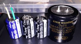
1. I left the factory installed 2200 uF 35 V "Chang" branded capacitors installed.
2. I added a 0.47 uF MKP to the bottom of the board and left it there.
3. Then I added a Nichicon VX series 1000 uF 50V to the bottom of the board and left it there.
4. Then I left all of the above caps installed and used 16 AWG copper jumpers to install an external 10,000 uF 50V Nover "Audio" Power Supply filter capacitor. (It might be fake and I had removed it from an Ebay purchased power supply filter board that I then populated with known genuine caps.)
None of those made the big improvement. Now here is what made the big but not total improvement:
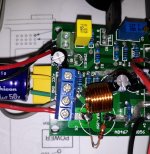
Next I removed all of the above and installed an inductor (and parallel 10 Ohm) resistor like a jumper where the original factory installed 2200 uF 35 V "Chang" branded output capacitor was installed.
I did this because I am afraid of oscillation with the genuine TTC004 driver and LJM kit D1047 outputs installed in one channel. (I had also earlier removed the 2SA1015 input transistor and soldered a genuine KTC1845 input transistor to the bottom of the board.)
I made the same changes to the other channel which is genuine TTC004 driver with genuine TIP35C outputs. Both channels had a similar sound and similar distortion.
For the output capacitor I used the "out" terminal to connect the same 10,000 uF 50V Nover "Audio" Power Supply filter capacitor. (With the same 0.47 uF MKP soldered to the terminals of the cap.)
The difference is striking but I am not sure why.
Is it because I installed the inductor (paralleled by the 10 Ohm) due to fear of oscillation?
Or is it because I removed the 2200 uF 35V "Chang" factory installed output cap? (The "Chang" caps on each board look a little different on the bottom, see photo.)
I have enclosed pictures of the capacitors and the location of the "jumper" over the original output capacitor location (inductor and 10 Ohm).
As shipped there was an unpleasant distortion with what I will call loud or dense mixes such as hard rock. My latest change significantly improved this but I am not sure why. Before the change there seems to be a combination of a mid and high freq and fatiguing distortion. Plus an unpleasant characteristic a bit like a mild cold or slightly plugged ears. (I find it hard to describe.) None of this is gone now, however it is quite a bit better.
So the problems were present as shipped and were not really much improved with the changes I had made which including the following for the output caps:
1. I left the factory installed 2200 uF 35 V "Chang" branded capacitors installed.
2. I added a 0.47 uF MKP to the bottom of the board and left it there.
3. Then I added a Nichicon VX series 1000 uF 50V to the bottom of the board and left it there.
4. Then I left all of the above caps installed and used 16 AWG copper jumpers to install an external 10,000 uF 50V Nover "Audio" Power Supply filter capacitor. (It might be fake and I had removed it from an Ebay purchased power supply filter board that I then populated with known genuine caps.)
None of those made the big improvement. Now here is what made the big but not total improvement:
Next I removed all of the above and installed an inductor (and parallel 10 Ohm) resistor like a jumper where the original factory installed 2200 uF 35 V "Chang" branded output capacitor was installed.
I did this because I am afraid of oscillation with the genuine TTC004 driver and LJM kit D1047 outputs installed in one channel. (I had also earlier removed the 2SA1015 input transistor and soldered a genuine KTC1845 input transistor to the bottom of the board.)
I made the same changes to the other channel which is genuine TTC004 driver with genuine TIP35C outputs. Both channels had a similar sound and similar distortion.
For the output capacitor I used the "out" terminal to connect the same 10,000 uF 50V Nover "Audio" Power Supply filter capacitor. (With the same 0.47 uF MKP soldered to the terminals of the cap.)
The difference is striking but I am not sure why.
Is it because I installed the inductor (paralleled by the 10 Ohm) due to fear of oscillation?
Or is it because I removed the 2200 uF 35V "Chang" factory installed output cap? (The "Chang" caps on each board look a little different on the bottom, see photo.)
I have enclosed pictures of the capacitors and the location of the "jumper" over the original output capacitor location (inductor and 10 Ohm).
Attachments
Last edited:
What is your supply voltage, quiescent current and speaker impedance? Was U / 2 checked at the exit? Twisted pair (screen) at the input? Pinout KTC1845? NPN or PNP 1015?
Replace the TYP41c driver?
Replace the TYP41c driver?
Last edited:
I hate to say it, but this is where a 'scope shines and you could then probably identify what type of misbehaviour the amplifiers are actually up to. To attempt some answers, the coil/resistor combo is unlikely to cause problems but I wouldn't use it when there is already a massive output cap. in series, as that forms a likely nasty (even if damped) resonant circuit.
Though I'm not clear on what parts you have to work with, I'd revert to original condition and retest each module to be certain whether they both have the same problem. Then you'll know whether it's a parts quality/design problem or its an error, bad part, soldering etc. Replacing the TTC004 with something slower would be a better way to check for oscillation if you have no direct means of checking it. Maybe BD139 or even 2N5551 would be ok to use for a brief test at low output level.
Though I'm not clear on what parts you have to work with, I'd revert to original condition and retest each module to be certain whether they both have the same problem. Then you'll know whether it's a parts quality/design problem or its an error, bad part, soldering etc. Replacing the TTC004 with something slower would be a better way to check for oscillation if you have no direct means of checking it. Maybe BD139 or even 2N5551 would be ok to use for a brief test at low output level.
- Home
- Amplifiers
- Solid State
- JLH 10 Watt class A amplifier