R27/c6 and R28/C7 provide HF isolation between the pre-driver and driver stages. If you layout is very good (short low inductance tracks etc) you can possibly get away without these devices. If the track inductances are high, the pre-driver and driver can form a Colpitts oscillator structure and you get instability. I did a lot of testing on my e-amp (EF3 OPS) on this subject and concluded this network gave important benefits.
Thank you Andrew for you very good explanation.
I did not try a triple without it, but you are very right about layout influence.
Thanks your guys, I have learnt a new useful thing.
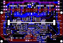
I'm nearly done with the PCB. I plan to bring it to PCB company at Monday next week.
It looks very good. It is not easy to follow the connection on a double sides board and I can't say if there could be some improvement, but if I can suggest to make possible for different dimension(footprint 15 mm and 20 mm at least) caps C26 and C27. Not every body will find the same caps.
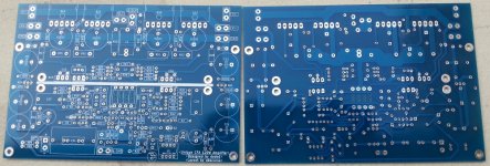
My boards come today. Finally, I can start working on the design.
Also have some questions.
- I only have R12 = 10 / 8.2 ohms. Could I use them or I need to change value of C1?
- Could I use L1 = 1uH ?
Also have some questions.
- I only have R12 = 10 / 8.2 ohms. Could I use them or I need to change value of C1?
- Could I use L1 = 1uH ?
Attachments
My boards come today. Finally, I can start working on the design.
Also have some questions.
- I only have R12 = 10 / 8.2 ohms. Could I use them or I need to change value of C1?
- Could I use L1 = 1uH ?
You can use R12 = 8.2 ohm, but I prefer 6.8 ohm, no need to change C1.
You can use 1 uH, but 0.5 uH is more then enough and has less on sound influence.
By the way, nice boards.
mcd99;4105871 Some CFAs don't use a CMCL or the current mirror alternative so these could suffer from the symmetrical VAS fighting issue. This was discussed in the CFA thread along with the current mirrors being used for compensation as well. Followed the CFA thread from the beginning so never needed to wade. However said:For those wanting a quick answere for what and how a CFA is defined in operation, that CFA thread has it all..... if you sort just by my name there, you will find many books referred to about CFA. Some insights will be found why they can have very low distortion using low circuit Z values and current operated stage advantage vs voltage operated.
With the 200W FET OPS using 4 Ohm load and 5KHz at 112W, I measured (yesterday) <-105dB THD; At 1KHz better than -110dB THD. Almost entirely 2H.
THx-RNMarsh
I made a stupid mistake with the PCB. I swap the Anot and Katot of the output transitor. So I took me a while to debug the problem.
I had one channel working today, I'm not solder the DC servo yet and the DC offset was about 70mV. I will finish the rest and do some listening test.
I had one channel working today, I'm not solder the DC servo yet and the DC offset was about 70mV. I will finish the rest and do some listening test.
I made a stupid mistake with the PCB. I swap the Anot and Katot of the output transitor. So I took me a while to debug the problem.
I had one channel working today, I'm not solder the DC servo yet and the DC offset was about 70mV. I will finish the rest and do some listening test.
Don't worry about mistakes, I do it almost always with first layout.
I am waiting for your listening test. You are the first one to build this amp, I did the mosfet version only.
Don't worry about mistakes, I do it almost always with first layout.
I am waiting for your listening test. You are the first one to build this amp, I did the mosfet version only.
Yeah. At least it is working now. Bias is rock solid stable. I will play with it a bit more before bring it to one of my friend house which have better speaker and DAC than mine.
I have some questions about this amp:
1. I saw the heatsink of the drivers (2mm alu) connect to ground in your PCB version, mine is not. Do I need to connect it to GND?
2. I set bias = 100ma. Is it the optimum bias point?
3. Is there a way to fight high dc offset without dc servo?
4. What is the value of your gound breaking resitor? 10r ?
4. Optimum voltage will be +-50V, right?
1.Better connect it to the ground, in that way it plays some isolation role between OPS and IPS.
2. 100 mA is OK, 25 mV/Re
3. Not easy way as there is not possible to have perfect complements between npn and pnp transistors.
4. Not critical, 10R is OK.
5. Depends of the loudspeakers impedance you are using, but with +-50V you are on save side. For very low impedance loudspeakers use lower, as +-40V.
I soldered the DC Servo part and it worked, my DC offset start from 70mV and decrease to 0.1mV, sonic degreration are not recognizable. Now I need to analyze the bias to make it arround 25 mV/Re.
About the input capacitor? Is it ok if I use a 2.2uf film cap?
I soldered the DC Servo part and it worked, my DC offset start from 70mV and decrease to 0.1mV, sonic degreration are not recognizable. Now I need to analyze the bias to make it arround 25 mV/Re.
About the input capacitor? Is it ok if I use a 2.2uf film cap?
With 2.2 uF you will get -3 dB gain drop at 3.2 Hz.
Re is emitter resistor + output transistor internal re + base stopper/beta, so I think that 100 mA for the bias is quite OK.
and Happy New Year to all
Last edited:
Obscurus, any listening impression yet?
Damir
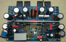
Hi, I'm slowly working on the project. My speaker was not so good but after listening to this CFA amp, I found my old amps lacking something. This CFA sounded very details with really big soundstage, doesnt have some kind of micro delay in sound like my other amps, but the sound was a bit raw, I suppect it is may be because of the input capacitor. I plan to buy some jantzen superior-z cap to replace the current capacitor. But it definity the most music sounding amp in my collection. My wife liked it, too. I'm happy that I decided to build this amp.
I will have change to test it one better speaker and vs some diy amp in the close future. So please wait for my next listening impression.
Attachments
Hi, I'm slowly working on the project. My speaker was not so good but after listening to this CFA amp, I found my old amps lacking something. This CFA sounded very details with really big soundstage, doesnt have some kind of micro delay in sound like my other amps, but the sound was a bit raw, I suppect it is may be because of the input capacitor. I plan to buy some jantzen superior-z cap to replace the current capacitor. But it definity the most music sounding amp in my collection. My wife liked it, too. I'm happy that I decided to build this amp.
I will have change to test it one better speaker and vs some diy amp in the close future. So please wait for my next listening impression.
You can short input capacitor if your source does not have DC offset on the output.
You can short input capacitor if your source does not have DC offset on the output.
I will check my input about the DC offset and try that if possible. I also will try to access some oscilloscope.
I will check my input about the DC offset and try that if possible. I also will try to access some oscilloscope.
I've seen on Vietnam forum that you have changed something in the GainWire mk2. Could you show and explain that in the GainWire mk2 thread here in this forum, could be interesting for me and other builders?
I've seen on Vietnam forum that you have changed something in the GainWire mk2. Could you show and explain that in the GainWire mk2 thread here in this forum, could be interesting for me and other builders?
Oh, it is not that interesting! I made that topic just for show my progress. No one ever try to build it. I'm the only one that build that preamp it in my country. Others just ignore it and follow project like kaneda and NAC72.
After built that preamp, I found CFA topo sound is really what I want and decided to build an 120W CFA in this topic.
- Home
- Amplifiers
- Solid State
- Unique CFA 120/230W amp