Sorry if i made you feel uncomfortable. I knew that you are not available now.
I just want to provide info so you can look at it later.
I just want to provide info so you can look at it later.
Sorry if i made you feel uncomfortable. I knew that you are not available now.
I just want to provide info so you can look at it later.
Here is LTspice file of last schematic.
Attachments
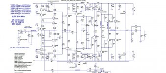
I run the last sch file and q5 / q7 was about 250mW still not excess the limit of 300mW so it is ok. But these are some changes in component values of:
C9, C10, R43, R54, C14, C5
since I already order these items based on old value, I will try with old values first.
C9, C10, R43, R54, C14, C5
since I already order these items based on old value, I will try with old values first.
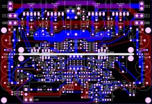
After a lot of great help from topic owner, I manage to create a PCB layout of the amp. I'm going to double check it and so some fine tunning until it hit the PCB company. Comments are welcome!
It looks good😊
What is pcb size?
Can you also make as an input board also as i have a slewmaster pcb with 2 pair output??
Best regards
It looks good��
What is pcb size?
Can you also make as an input board also as i have a slewmaster pcb with 2 pair output??
Best regards
I don't think it's good idea to have separate IPS board as the compensation is highly OPS dependent. I am not sure how it could behave with different OPS.
Damir
It looks good😊
What is pcb size?
Can you also make as an input board also as i have a slewmaster pcb with 2 pair output??
Best regards
PCB size is 161mm x 110mm.
Sorry about the other IPS PCB request, I just don't have extra time to do it.
I think I can:
- Set R43 = 300, C9=C10 = 220p, R54=47, C14=C15=22p. How do you think about this change? It is mainly because I already ordered the mica caps when I followed this schematic http://www.diyaudio.com/forums/solid-state/253039-unique-cfa-120-230w-amp-15.html#post4362435.
- Could I use BC560C/BC550C in Q25, Q26 because in sim, VCE ~ 26V ?
- Could I use BC560C/BC550C in Q25, Q26 because in sim, VCE ~ 26V ?
At this place BC546/556 are better performance wise, a least in my simulations of enhanced "VAS", look like beta matter less than high VCE as this transistor doesnt load the previous stage significantly compared to R2/R5.
Also their collectors should be decoupled in respect of the rail voltage to suppress the miller effect due to high values for R20/R24, at lower values decoupling is not needed.
I think I can:
- Set R43 = 300, C9=C10 = 220p, R54=47, C14=C15=22p. How do you think about this change? It is mainly because I already ordered the mica caps when I followed this schematic http://www.diyaudio.com/forums/solid-state/253039-unique-cfa-120-230w-amp-15.html#post4362435.
- Could I use BC560C/BC550C in Q25, Q26 because in sim, VCE ~ 26V ?
You an use the caps you have but for R43 use 220R, you will get phase margin somewhat lower.
BC560C/BC550C is not good enough. In case of clipping whole voltage will be between collector - emitter, 45V is max for those transistors.
At this place BC546/556 are better performance wise, a least in my simulations of enhanced "VAS", look like beta matter less than high VCE as this transistor doesnt load the previous stage significantly compared to R2/R5.
Also their collectors should be decoupled in respect of the rail voltage to suppress the miller effect due to high values for R20/R24, at lower values decoupling is not needed.
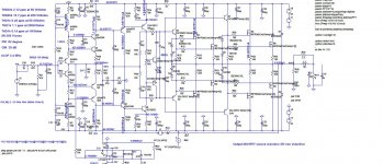
I don't know from which schematic R20/R4 are coming, but if you mean R49/R50, I simulated decupled collectors and THD20k at 100W/8 drops from 2.03 ppm to 1.99 ppm. I think it's not big enough gain so I did not use decoupling there.
I don't know from which schematic R20/R4 are coming, but if you mean R49/R50, I simulated decupled collectors and THD20k at 100W/8 drops from 2.03 ppm to 1.99 ppm. I think it's not big enough gain so I did not use decoupling there.
It was in one of your previous pic with the values at 15K, i simulated again your amp and it s right that they do not have a big influence in this design.
Attachments
It was in one of your previous pic with the values at 15K, i simulated again your amp and it s right that they do not have a big influence in this design.
That schematic is from other thread, 200W CFA MOSFET.
Thank you for your comments and suggestions.
Damir
Since 2sc970/2sc2240 are obsolete from Toshiba, can you suggest a sub?
I sub'd ksa992/ksc1845 in the sim and the thd #'s look to be the same.
I sub'd ksa992/ksc1845 in the sim and the thd #'s look to be the same.
Since 2sc970/2sc2240 are obsolete from Toshiba, can you suggest a sub?
I sub'd ksa992/ksc1845 in the sim and the thd #'s look to be the same.
They are OK, in practice too.
Sajti
http://www.diyaudio.com/forums/solid-state/253039-unique-cfa-120-230w-amp-19.html#post4458063
I'm still working on the PCB but I have some questions about the design:
Could you tell me the purpose of R27/C6 and R28/C7 ?
And is it better to put them before Q13/Q14 rather than Q5/Q7 ?
I'm still working on the PCB but I have some questions about the design:
Could you tell me the purpose of R27/C6 and R28/C7 ?
And is it better to put them before Q13/Q14 rather than Q5/Q7 ?
http://www.diyaudio.com/forums/solid-state/253039-unique-cfa-120-230w-amp-19.html#post4458063
I'm still working on the PCB but I have some questions about the design:
Could you tell me the purpose of R27/C6 and R28/C7 ?
And is it better to put them before Q13/Q14 rather than Q5/Q7 ?
Bob Cordell suggested that to be between pre drivers and drivers in some thread(I don't remember what one it was). I used in that way in my working ThermalTrak amp.
R27/c6 and R28/C7 provide HF isolation between the pre-driver and driver stages. If you layout is very good (short low inductance tracks etc) you can possibly get away without these devices. If the track inductances are high, the pre-driver and driver can form a Colpitts oscillator structure and you get instability. I did a lot of testing on my e-amp (EF3 OPS) on this subject and concluded this network gave important benefits.
- Home
- Amplifiers
- Solid State
- Unique CFA 120/230W amp