...What do you think about to open a new thread...
I will try to show how I decided what circuits to use, but I need a time to collect all my different simulation burred in to many files.
I think a new thread is an excellent idea, but I needed time to prepare too.
So I just planned to have some preliminary discussions first, start to think about it before I opened a new thread with detailed simulation.
But that is just my style, whatever is best for you, still interested in your ideas even if your ASCs are buried, my LTspice machine must be fixed first anyway.
I am in accord that we should start with complementary circuit and I also like the idea of simplification.
In fact, I think the main benefit of "CFA" is possible simplification.
Best wishes
David
Last edited:
That CFA... (?) I showed some post back I like more and more...
I define it as _not_ a "CFA" because the essential element of a "CFA" is the low impedance feedback node.
I prefer your "CFA" version, the VFA has almost double the complexity in the IPS and the distortion is already so low that any improvement will be totally inaudible.
Also, I use very sensitive compression drivers so I am more concerned than usual about noise, and it will be worse. Perhaps inaudible too but the CFA should have substantially lower noise and the cost in distortion is tiny.
My main objective is to see how much I can simplify and still keep the distortion and noise low. Say below 0.001% @ 20 kHz at nominal power.
The main area that "CFA" differ from VFA is how to load the IPS and connect it to the VAS/TIS, what do you see as the trade-offs of the different schemes?
Best wishes
David
Hi David,
Those small transistors are cheap and the feedback network is not any more low impedance (that was advantage but..) and does not dissipate a lot of energy. If you look at the layout it quite complicate because the need for high power resistors (I solved it by paralleling 11 two watts resistors) , more that 10 W in that case, and feedback path get longer and that is not so good. For high impedance feedback network 1 W resistor is adequate. Regarding noise, the feedback resistors are still quite low, no need to have the same resistance as at the input. The load of the IPS and connection to VAS/TIS is equal, I don't see the problem there.
I am for simplicity, but up to the point.
best regards
Damir
Those small transistors are cheap and the feedback network is not any more low impedance...
Yes, definite trade-off in the low impedance feedback network.
Even a VFA can have a low impedance feedback network and I have checked this with simulation.
It has the benefits of low noise and increased IPS pole frequency, just like a "CFA", and the same cost of wasted power too.
So my limit here is set by my environmental conscience, what I can accept as waste, rather than by circuit problems.
As you say, transistors are cheap, but so are resistors😉
It is not the cost of a few transistors or resistors, of course.
Mainly the extra risk of mistakes in assembly, failures in service, less compact PCB, more complexity if there are problems, and so on.
So we both try to achieve a reasonable balance.
No problem except I was not clear... The load of the IPS and connection to VAS/TIS is equal, I don't see the problem there.
I just meant that it was common to load the VFA LTP transistors with resistors or a current mirror (hi Z), maybe with cascode.
For a "CFA" a current mirror makes no sense, but we can have the CE transistors work into
1. Resistors or
2. A current source (hi Z) or
3. A current conveyor to the VAS or
4. Other possibilities?
maybe with cascode.
And some of these interact with the VAS options.
A current conveyor is an easy fit with a Hawksford cascode VAS.
An EF assisted VAS is probably easier with other interconnection choices.
I notice you have simulated many of these combinations, wondered about your ideas.
Best wishes
David
Yes, definite trade-off in the low impedance feedback network.
Even a VFA can have a low impedance feedback network and I have checked this with simulation.
It has the benefits of low noise and increased IPS pole frequency, just like a "CFA", and the same cost of wasted power too.
So my limit here is set by my environmental conscience, what I can accept as waste, rather than by circuit problems.
As you say, transistors are cheap, but so are resistors😉
It is not the cost of a few transistors or resistors, of course.
Mainly the extra risk of mistakes in assembly, failures in service, less compact PCB, more complexity if there are problems, and so on.
So we both try to achieve a reasonable balance.
No problem except I was not clear
I just meant that it was common to load the VFA LTP transistors with resistors or a current mirror (hi Z), maybe with cascode.
For a "CFA" a current mirror makes no sense, but we can have the CE transistors work into
1. Resistors or
2. A current source (hi Z) or
3. A current conveyor to the VAS or
4. Other possibilities?
maybe with cascode.
And some of these interact with the VAS options.
A current conveyor is an easy fit with a Hawksford cascode VAS.
An EF assisted VAS is probably easier with other interconnection choices.
I notice you have simulated many of these combinations, wondered about your ideas.
Best wishes
David
Hi David,
I think that you go to fast, I hoped for a step by step analysis of each amp part and possibilities of improvements/simplification.
I simulated some of combination I thought to be good, part is here http://www.diyaudio.com/forums/solid-state/243481-200w-mosfet-cfa-amp-43.html#post3753533 and came to conclusion that for CFA the best return I getting with simple resistor load for IPS and end enhanced (EF to drive VAS/TIS, actually first I choose simple VAS but letter found solution for enhaced one ) as this is easy to compensate and gives very high loop gain, specially if VAS emitter's resistor is replaced with a diode.
With all other combination I tried I've got no better result or I could not compensate satisfactory.
I simulated with active IPS load with very high LG, but again problem with compensation.
Current mirrors acting as a current conveyor is also good solution specially if you go for NGNFB.
By the way when I said that small transistors are cheap (resistors are cheap to but high power ones are bulky and take more space and make longer feedback path) I meant it will not make the amp more expensive.
best regards
Damir
...to[o] fast, I hoped for a step by step analysis of each amp part and possibilities of improvements/simplification.
Too fast !? I just try to catch up with what you have already done😉
I plan a careful analysis but first wanted to have an overview, otherwise I don't know where to start.
But I will try to do as you hope, can you be more specific?
...came to conclusion that for CFA the best return I getting with simple resistor load for IPS and end enhanced (EF to drive VAS/TIS
I have found EF assisted VAS worked best in VFA and I notice Toni (ASTX) reported the same conclusion in your other thread.
So that looks like the first circuit to try.
... a current conveyor is also good solution specially if you go for NGNFB.
A conveyor fits naturally with a cascoded VAS, don't think I've seen an EF assisted conveyor. Need to think if that's because there is a problem.
Why does NFB make a difference in this case?
...resistors ...take more space...
I plan to use the resistors to cover the distance to the IPS, so not much PCB trace except for the resistors in series.
Small side benefit that the series connection lowers any nonlinearities because the potential across each resistor is reduced.
Bruce Hofer (Audio Precision) says this makes a difference at PPM levels.
Not audible but nice to have better numbers when it's no extra cost.
Best wishes
David
I am in accord that we should start with complementary circuit and I also like the idea of simplification.
In fact, I think the main benefit of "CFA" is possible simplification.
Best wishes
David
😎🙂
....... and ease of compensation.
THx-RNMarsh
Last edited:
Too fast !? I just try to catch up with what you have already done😉
I plan a careful analysis but first wanted to have an overview, otherwise I don't know where to start.
But I will try to do as you hope, can you be more specific?
I have found EF assisted VAS worked best in VFA and I notice Toni (ASTX) reported the same conclusion in your other thread.
So that looks like the first circuit to try.
A conveyor fits naturally with a cascoded VAS, don't think I've seen an EF assisted conveyor. Need to think if that's because there is a problem.
Why does NFB make a difference in this case?
I plan to use the resistors to cover the distance to the IPS, so not much PCB trace except for the resistors in series.
Small side benefit that the series connection lowers any nonlinearities because the potential across each resistor is reduced.
Bruce Hofer (Audio Precision) says this makes a difference at PPM levels.
Not audible but nice to have better numbers when it's no extra cost.
Best wishes
David
Hi David,
I haven't seen an EF assisted conveyor ether, but I used conveyor in my pre amp (GainWire mk2) in NGNFB configuration with very low distortion.
Regarding resistor voltage distortion I don't think it's an issue to go for series connected feedback resistor, but in that way you make the feedback path quite longer and that could be an issue.
I don't think you need to catch me, you are in many ways ahead of me.
best regards
Damir
Last edited:
... and ease of compensation.
I don't see any evidence for that claim, in the context of audio amplifiers.
It is a bit easier for the user in op-amps, where the manufacturer can make a product that will work well over a reasonable spread of different gains for different user requirements. Probably about the same for the manufacturer.
But for audio amps, where the gain is essentially fixed and we are the manufacturer, the compensation does not look any easier.
Damir's amp in this thread is an excellent example, it does not have simple compensation.
You can read Damir's earlier 200W CFA thread to see how hard he worked to do the compensation, with whatever help I and several other could provide.
Best wishes
David
Last edited:
I don't see any evidence for that claim, in the context of audio amplifiers.
It is a bit easier for the user in op-amps, where the manufacturer can make a product that will work well over a reasonable spread of different gains for different user requirements. Probably about the same for the manufacturer.
But for audio amps, where the gain is essentially fixed and we are the manufacturer, the compensation does not look any easier.
Damir's amp in this thread is an excellent example, it does not have simple compensation.
You can read Damir's earlier 200W CFA thread to see how hard he worked to do the compensation, with whatever help I and several other could provide.
Best wishes
David
Hi David,
I think that Richards knows very well 200W CFA amp, he measured it, and he followed that thread too.
Probably he meant how easy to get very good PM and GM with quite simple compensation? And to come to that "simplicity", I am grateful for all help I've go. It can looks complicated because of symmetry.
Best Regards
Damir
...Probably he meant how easy to get very good PM and GM with quite simple compensation?...It can looks complicated because of symmetry.
Yes, the symmetry adds a few components but if we overlook that detail then I still would not call it simple.
Both Output Inclusive Compensation and TPC plus an extra zero around the VAS, with a little shunt on the bases of the EF drivers.
Does not meet my definition of simple😉.
My definition is that it can be worked out on the back of an envelope.
Not a criticism of your compensation, any optimized amp will have a little more complexity in the compensation, my VFA amp is similar
Point is just that "CFA" has no special properties in this respect.
The PM and GM are entirely functions of the return ratio, if the amp is Minimum Phase, and both VFA and "CFA" are normally close to MP.
Maybe "CFA" is more prone to have a transistor capacitance replace an actual capacitor?
That would look a little simpler but maybe actually harder to understand because not obvious.
Best wishes
David
Last edited:
That CFA with high impedance -input (?) I showed some post back I like more and more. It is easy to make it to work without DC servo just adding series capacitor to the feedback resistor R57 just as in VFA.
I define it as _not_ a "CFA" because the essential element of a "CFA" is the low impedance feedback node.
I prefer your "CFA" version, the VFA has almost double the complexity in the IPS and the distortion is already so low that any improvement will be totally inaudible.
Also, I use very sensitive compression drivers so I am more concerned than usual about noise, and it will be worse. Perhaps inaudible too but the CFA should have substantially lower noise and the cost in distortion is tiny.
My main objective is to see how much I can simplify and still keep the distortion and noise low. Say below 0.001% @ 20 kHz at nominal power.
The main area that "CFA" differ from VFA is how to load the IPS and connect it to the VAS/TIS, what do you see as the trade-offs of the different schemes?
Best wishes
David
I think Dave is on the money, this is a voltage feedback amp.
I would suggest you (Dadod) build it and check thermal stability. That
symmetrical front end is always alluring and adding gain on both + - sides
gives you nice low distortion but just step back for a minute and think it through.
There will be very good chance of thermal runaway as both sides heat up
and the current running through VAS and VBE multiplier may have a
tendency to skyrocket.
It's always easy on simulations to get bucket loads of OLG but to get it to
work in -real life- with VG stability is a different story.
T
Do you mean because the added high impedance -input could provoke thermal runaway, or even as pure CFA with low impedance -input only?
Hi David,
Probably he meant how easy to get very good PM and GM with quite simple compensation?
Best Regards
Damir
 yes.
yes.-RNM
Originally Posted by zenelectro
I think Dave is on the money, this is a voltage feedback amp.
I would suggest you (Dadod) build it and check thermal stability. That
symmetrical front end is always alluring and adding gain on both + - sides
gives you nice low distortion but just step back for a minute and think it through.
There will be very good chance of thermal runaway as both sides heat up
and the current running through VAS and VBE multiplier may have a
tendency to skyrocket.
It's always easy on simulations to get bucket loads of OLG but to get it to
work in -real life- with VG stability is a different story.
T
You did not answered my question. I think you wrong about thermal runaway here.
An externally hosted image should be here but it was not working when we last tested it.
I think Dave is on the money, this is a voltage feedback amp.
I would suggest you (Dadod) build it and check thermal stability. That
symmetrical front end is always alluring and adding gain on both + - sides
gives you nice low distortion but just step back for a minute and think it through.
There will be very good chance of thermal runaway as both sides heat up
and the current running through VAS and VBE multiplier may have a
tendency to skyrocket.
It's always easy on simulations to get bucket loads of OLG but to get it to
work in -real life- with VG stability is a different story.
T
Do you mean because the added high impedance -input could provoke thermal runaway, or even as pure CFA with low impedance -input only?
You did not answered my question. I think you wrong about thermal runaway here.
Hi.
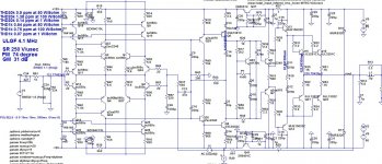
I want to know some params of the design:
1. Current for Q25 / Q26 ?
2. Current for Q6 / Q8 ? 7.8ma ?
3. Current for Q5 / Q7 ? In SIM, i get 4.5mA -> 247mA -> Is it a bit high for 2SC2240 / 2SA970 ?
I want to know some params of the design:
1. Current for Q25 / Q26 ?
2. Current for Q6 / Q8 ? 7.8ma ?
3. Current for Q5 / Q7 ? In SIM, i get 4.5mA -> 247mA -> Is it a bit high for 2SC2240 / 2SA970 ?
Hi.
I want to know some params of the design:
1. Current for Q25 / Q26 ?
2. Current for Q6 / Q8 ? 7.8ma ?
3. Current for Q5 / Q7 ? In SIM, i get 4.5mA -> 247mA -> Is it a bit high for 2SC2240 / 2SA970 ?
I will give that data next week when I am backhome.
What simulator you use?
I will give that data next week when I am backhome.
What simulator you use?
I use LTSpice. I downloaded an old sch in this thread and modified it to match the schematic that I'm going to layout. I did change the VR to set the bias of output bjt to100ma each. Here is what i got:
Super pairs = 1.32mA
Q1/Q2 = 3mA
Q6/Q8 = 13.2mA
Q5/Q7 = 4.3mA
Q13/Q14 = 32mA
I use LTSpice. I downloaded an old sch in this thread and modified it to match the schematic that I'm going to layout. I did change the VR to set the bias of output bjt to100ma each. Here is what i got:
Super pairs = 1.32mA
Q1/Q2 = 3mA
Q6/Q8 = 13.2mA
Q5/Q7 = 4.3mA
Q13/Q14 = 32mA
As I said I cant help younow, I will attached last LTspice file next week.
- Home
- Amplifiers
- Solid State
- Unique CFA 120/230W amp