Hi,
I used the Jantzen Superior Z as input cap and it work great.
In the second channel, I use the new method for matching trans and get 17->22mV dc offset and change very much. Is it good enough to not use dc servo?
For low efficient loudspeaker this os OK, but for very high efficient loudspeaker could be to much, but why not to use DC servo if it's on the board already.
What is new method for transistor matching?
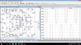
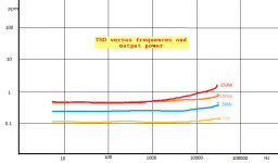
This is just a exercise to see how low THD can go in this CFA configuration. This is only simulation and I don't expect that the sound will be better then previous schematic. THD20K is below 1ppm on all output power even with 4 ohm load. This amp has THD on all audio frequencies and at all output power below 1ppm.
Damir
I was asked to use non switching OPS. This is one try, but if I push the OPS to non switch work I've got higher distortion then if non switch was not used. With some more simulation I came to something in between and with lower THD. Now the amp has quite low distortion and practically distortion does not change with frequency or output power, just straight line below 1 ppm.
To see improvement I attached both schematics with no non switching circuit and with it.
Attachments
Last edited:
This amp is pushed to the maximum by using active load for IPS.
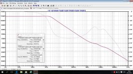
LTspice shows THD1k at zero at all output level, and THD20k is halved.
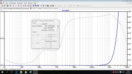
Loop gain looks much like VFA, but have other characteristics typical for CFA.
Damir
LTspice shows THD1k at zero at all output level, and THD20k is halved.
Loop gain looks much like VFA, but have other characteristics typical for CFA.
Damir
Attachments
-
 120W-TT-CFA-triple-TPOIC-efVAS-RC-22-0.47u-currmirr_sch.jpg142.1 KB · Views: 736
 -
 120W-TT-CFA-triple-TPOIC-efVAS-RC-22-0.47u-currmirr_LG.jpg249.8 KB · Views: 700
 -
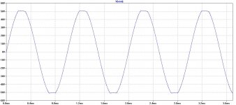 120W-TT-CFA-triple-TPOIC-efVAS-RC-22-0.47u-currmirr_clipping.jpg97.7 KB · Views: 619
 -
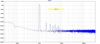 120W-TT-CFA-triple-TPOIC-efVAS-RC-22-0.47u-currmirr_FFT1k1W.jpg126.7 KB · Views: 242
 -
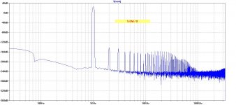 120W-TT-CFA-triple-TPOIC-efVAS-RC-22-0.47u-currmirr_FFT1k50W.jpg130.8 KB · Views: 274


Hi Guys
The Wilson mirror on the negative circuit half sets the voltage at the EF-VAS base and thus sets the idle current for the VAS. The standard mirror on the positive side just follows what the bottom has done. I suggested this in the Cordell thread where people were debating how to use mirrors in a fully complementary amp. Self took a different approach with a simple mirror on one side and resistive loading on the other. With identical mirrors the idle current is nebulous.
Have fun
That is improved Wilson current mirror, but could be used ordinary Wilson current mirror with very similar result and one transistor less.
Hi Guys
Just a clarification of what I said in post-246:
The bottom mirror does not set the current of the VAS per se rather it imposes a well-defined voltage at the base of the EF feeding the VAS.
As with all CFAs with a diamond input, the current source for the input stage sets the current through the diamond. This output current flows through R36 of the Wilson mirror and is reflected through to the upper mirror. The lower mirror imposes two Vbe drops between R36 and the diamond output. The BJTs of the EF-VAS take up both of these drops and what is left is across R16 of the VAS, equal to the voltage drop across R36. In this way, the VAS current is directly proportional to the input stage current source.
Have fun
Hi Guys
Just a clarification of what I said in post-246:
The bottom mirror does not set the current of the VAS per se rather it imposes a well-defined voltage at the base of the EF feeding the VAS.
As with all CFAs with a diamond input, the current source for the input stage sets the current through the diamond. This output current flows through R36 of the Wilson mirror and is reflected through to the upper mirror. The lower mirror imposes two Vbe drops between R36 and the diamond output. The BJTs of the EF-VAS take up both of these drops and what is left is across R16 of the VAS, equal to the voltage drop across R36. In this way, the VAS current is directly proportional to the input stage current source.
Have fun
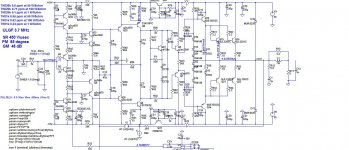
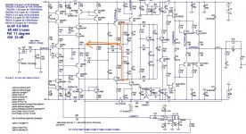
This diamond input is not typical diamond connection as it uses supper pairs (collectors of Q11, Q12 are not powered from the opposite polarities).
The current sources set the current trough Q3, Q4(and corresponding cascode transistors), but the VAS current was set by selecting proper current mirrors resistor value. I prefare to have it in range from 4 to 6 mA.
Resistor R60 could be omitted, but in this case Q10 will see almost the full power supply voltage.
Last edited:
I was asked to use non switching OPS. This is one try, but if I push the OPS to non switch work I've got higher distortion then if non switch was not used.
Excuse my question, what makes this output stage "non switching"?
Excuse my question, what makes this output stage "non switching"?
I tried to simulate simple non switching OPS and somebody on this forum suggested something from commercial production. I did not liked the result and did not persuade farther.
Attachments
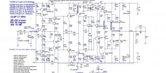
Some more exploration of this topology, now with added nested NFB around IPS and VAS. The Lopp Gain is 60 dB and flat up to 60 kHz.
I am not sure if this configuration will sound better, more close to live music, but here it is.
Damir
I am not sure if this configuration will sound better, more close to live music, but here it is.
Damir
Attachments
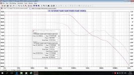
Some more exploration of this topology, now with added nested NFB around IPS and VAS. The Lopp Gain is 60 dB and flat up to 60 kHz.
I am not sure if this configuration will sound better, more close to live music, but here it is.
Damir
Looks good, are you sure the IPS is stable when it build?
Thx
Looks good, are you sure the IPS is stable when it build?
Thx
You are right, internal VAS/IPS loop does not look stable.
I have to think how to make it stable.
Attachments
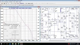
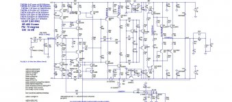
This amp is pushed to the maximum by using active load for IPS.
LTspice shows THD1k at zero at all output level, and THD20k is halved.
Loop gain looks much like VFA, but have other characteristics typical for CFA.
Damir
AFAICS, with the active load, there is no clearly defined DC conditions for VAS.
You need to implement a CMCL (common mode control loop) to control DC
conditions for VAS. This will add considerable complexity.
No free lunch or in this case free loop gain. 🙂
Z
AFAICS, with the active load, there is no clearly defined DC conditions for VAS.
You need to implement a CMCL (common mode control loop) to control DC
conditions for VAS. This will add considerable complexity.
No free lunch or in this case free loop gain. 🙂
Z
This amp is pushed to the maximum by using active load for IPS.
LTspice shows THD1k at zero at all output level, and THD20k is halved.
Loop gain looks much like VFA, but have other characteristics typical for CFA.
Damir
PS, You could always go back to previous design and try bootstrap load of Q25 / 26 with capacitors. Sort of like Greg Balls SKA amp.
This should add OLG but retain DC conditions for VAS.
Z
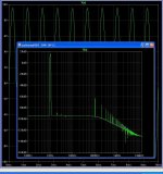
I not so masterfully use LTspice to get rid of artifacts after 100 kHz, but my amplifier is 3 times simpler. Coefficient of harmonicas 0.0003. I don't plan the scheme to discussion, it in the course of production yet.
Prompt how to fill in the directive LTspice for the correct display?
Prompt how to fill in the directive LTspice for the correct display?
Attachments
AFAICS, with the active load, there is no clearly defined DC conditions for VAS.
You need to implement a CMCL (common mode control loop) to control DC
conditions for VAS. This will add considerable complexity.
No free lunch or in this case free loop gain. 🙂
Z
No problem with VAS DC condition with this CMs.
I tried a CMLC with not so good result as it was not so easy to compensate.
- Home
- Amplifiers
- Solid State
- Unique CFA 120/230W amp