Oh, it is not that interesting! I made that topic just for show my progress. No one ever try to build it. I'm the only one that build that preamp it in my country. Others just ignore it and follow project like kaneda and NAC72.
After built that preamp, I found CFA topo sound is really what I want and decided to build an 120W CFA in this topic.
I think that you changed BD139/140 for some other transistors and measured the THD, did you?
I think that you changed BD139/140 for some other transistors and measured the THD, did you?
No, I still use B139/BD140 pair, I planed but didn't have time to do so.
I have q6 & q8 attach to the driver's heatsink. Is it going to be a problem or not optimizing action?
I have q6 & q8 attach to the driver's heatsink. Is it going to be a problem or not optimizing action?
You mean the VAS transistors?
I never tried that, normally I don't use heat sinks for the VAS transistors. Sometimes you need small separate heat sinks for them.
The drivers power dissipation is much higher then the VAS and in that case you heat the VAS transistors on higher temperature and I don't like that, but it should not change much electronically. Q23(Vbe multiplier) should be on the same heat sink with the drivers.
Yes. I just fixed it by bend them 45 degrees so they wasnt on driver heatsink anymore. Im working on second board while wait for the new input capacitor.
I recheck all bias of the amp and encounter a problem.
Bias for Q13 / Q14 = 2SC4883 / 2SA1859 (MJE15032 / MJE15033) was too high. I measured 100mV over R18 (1 ohm) => 100mA. And driver heatsink was too hot. What is the designed bias for these transistor? Increaser R18 will fix this?
I also measure ouput bias when short input. Is it the right way to do so?
I recheck all bias of the amp and encounter a problem.
Bias for Q13 / Q14 = 2SC4883 / 2SA1859 (MJE15032 / MJE15033) was too high. I measured 100mV over R18 (1 ohm) => 100mA. And driver heatsink was too hot. What is the designed bias for these transistor? Increaser R18 will fix this?
I also measure ouput bias when short input. Is it the right way to do so?
In the simulation that current is about 32 mA, and the value between 30 to 40 mA is OK. Probably TT diodes are a bit different in your TT transistors. Try to increase R18 up to 4R7.
In the simulation that current is about 32 mA, and the value between 30 to 40 mA is OK. Probably TT diodes are a bit different in your TT transistors. Try to increase R18 up to 4R7.
Thanks,
I already tried with some value, with 4R7 it is 17mA so I think I will try 2R2, it may be the value I need. Change R18 need output bias adjustment again to bring it back to 100mA.
Thanks,
I already tried with some value, with 4R7 it is 17mA so I think I will try 2R2, it may be the value I need. Change R18 need output bias adjustment again to bring it back to 100mA.
Yes of course, you need to re adjust output bias.
This CFA sounded very details with really big soundstage, doesnt have some kind of micro delay in sound like my other amps, but the sound was a bit raw, ........ But it definity the most music sounding amp in my collection. My wife liked it, too. I'm happy that I decided to build this amp.
😎🙂
-RNM
It is not about the R18 value problem. I have one transitor not close to the heatsink so bias skyrocket. So nothing need to change.
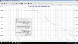
This is just a exercise to see how low THD can go in this CFA configuration. This is only simulation and I don't expect that the sound will be better then previous schematic. THD20K is below 1ppm on all output power even with 4 ohm load. This amp has THD on all audio frequencies and at all output power below 1ppm.
Damir
Damir
Attachments
This is just a exercise to see how low THD can go in this CFA configuration. This is only simulation and I don't expect that the sound will be better then previous schematic. THD20K is below 1ppm on all output power even with 4 ohm load. This amp has THD on all audio frequencies and at all output power below 1ppm.
Damir
Great work☺
Can you tell a bit what you did?
Maybe you can go lower in THD with a non switching output stage☺
Best regards
Great work☺
Can you tell a bit what you did?
Maybe you can go lower in THD with a non switching output stage☺
Best regards
I tried non switching OPS but could not get lower THD than this. Probably I don't know how to set optimum bias for NS OPS, I'll try it soon again.
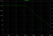
The main reason for so low 20 kHz THD is high GNFB at 20 kHz, look at the Loop Gain plot, it's flat up to 20 kHz. Additional improvement achieved adding C26 and C27.
Damir
Attachments
Hi Guys
I bet you would be surprised that you can hear a difference. Personally, I believe that all electronic distortion is quite unnatural inasmuch as it is not what we evolved to deal with, so even tiny bits of it can be detected.
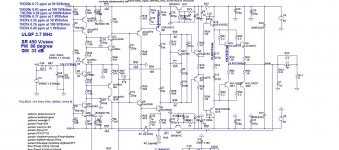
The schemo above seems to be cut off at the bottom.
I am always surprised by the roller coaster phase response that your circuits have. Maybe it is the multiple comp loops?
Have fun
I bet you would be surprised that you can hear a difference. Personally, I believe that all electronic distortion is quite unnatural inasmuch as it is not what we evolved to deal with, so even tiny bits of it can be detected.
The schemo above seems to be cut off at the bottom.
I am always surprised by the roller coaster phase response that your circuits have. Maybe it is the multiple comp loops?
Have fun
Hi Guys
I bet you would be surprised that you can hear a difference. Personally, I believe that all electronic distortion is quite unnatural inasmuch as it is not what we evolved to deal with, so even tiny bits of it can be detected.
The schemo above seems to be cut off at the bottom.
I am always surprised by the roller coaster phase response that your circuits have. Maybe it is the multiple comp loops?
Have fun
Bottom part is DC servo only. The roller coaster phase response is typical for two poles compensation.
Hi Damir,
just playing with CFA design as well. This would be the transfer impedance.
Hi Pavel,
Where would be that R18, I can't read your plot with no schematic?
- Home
- Amplifiers
- Solid State
- Unique CFA 120/230W amp