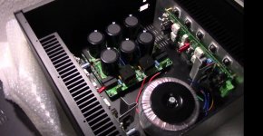
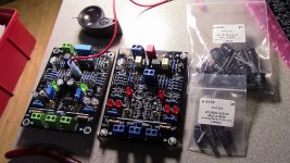
hi thimios hey you saw my build of the slewmaster? I still got a few more thing to go so it be completed after so many years now I can say I got something
Beautiful work

Super...!
hi thimios hey you saw my build of the slewmaster? I still got a few more thing to go so it be completed after so many years now I can say I got something
hi thimios hey you saw my build of the slewmaster? I still got a few more thing to go so it be completed after so many years now I can say I got something
cool!
I Hope this is an Acceptable Practice but ...
Hello all,
I am cleaning out my parts closet. I have lots of goodies that I won't be using and thought that I would share them with my fellow inmates on this forum. I've got Slewmaster PCBs and lots of power output devices. I don't expect them to last long. I invite you to stop buy and check them out.
Carl Huff is cleaning out his parts closet - Lots of goodies!
Wavetek Function Generator Model 110
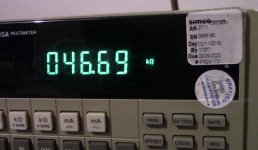
hi guys I already begin to purchase better test tools for my hobbies and I thinking to get me a vintage function generator will this be okay to just do simple 1KHz some wave test? I already purchase a DMM Fluke 8840A 5.5 digits to just get better reading on my resistors
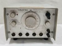
okay back to the function generator this is the one I know that it might not work but I'm more interested in something rugged that I can use for many years or let me know what is the best choice here is the unit picture Stuart told me about those cheap ones from EBay but they have some distortions I saw many videos about them
I ask first before I made a mistake here
hi guys I already begin to purchase better test tools for my hobbies and I thinking to get me a vintage function generator will this be okay to just do simple 1KHz some wave test? I already purchase a DMM Fluke 8840A 5.5 digits to just get better reading on my resistors
okay back to the function generator this is the one I know that it might not work but I'm more interested in something rugged that I can use for many years or let me know what is the best choice here is the unit picture Stuart told me about those cheap ones from EBay but they have some distortions I saw many videos about them
I ask first before I made a mistake here
Attachments
reference for feedback
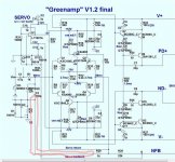
Hi,
I'am not sure at which position I should connect the reference for the feedback. There are two versions in different schematics:
1. In the Greenamp at ground of the Input (above the anti humm resistor R3)
2. In the Spooky at ground of the whole amp (G2)
Which one is right and why?
regards, Chris
Attachments
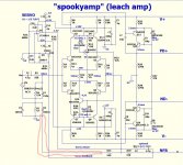
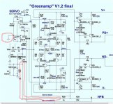
Servo setup is the following - as you need to keep zero DC across the speaker, and the speaker is connected to the "main" ground - you connect the servo's input reference to the main groung.
Now, if you've got a simple RC filter at the output of the servo (good practice, some 100R in series and 0.1uF to ground), then you connect the "bottom" side of this filter capacitor to the "signal ground".
Now, if you've got a simple RC filter at the output of the servo (good practice, some 100R in series and 0.1uF to ground), then you connect the "bottom" side of this filter capacitor to the "signal ground".
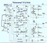
Hi valery and jwilhelm,
I made a simple grafik with your advice. Is this right now?
Wat is the background of the RC-Filter, is it against HF-oscillation?
We have a low pass filter R31, C9
C10 makes U1 an integrator stage.
The servo therefore only works at or near DC to correct long term drift.
If the servo received audio it would be akin to a dog chasing its tail!
Keith
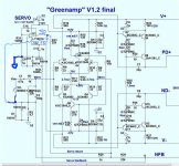
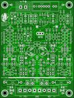
I'm not expert PCB designer but the Greenamp I made it just like the schematic said and I didn't have any problems at all I got the gerber files if you want it to try out the sounds is really good
they are two options of LED regular ones or SMD LED
they are two options of LED regular ones or SMD LED
Attachments
Last edited:
- Home
- Amplifiers
- Solid State
- Slewmaster - CFA vs. VFA "Rumble"