No , but there is the finished "SYMasui" .
Finally have it done ! 😱
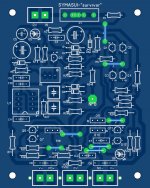
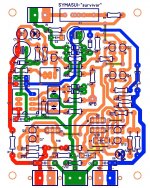
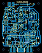
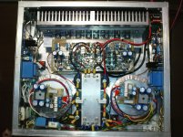
(below 1/2) is the "pretty " PCB.
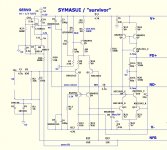
(below 3) is the schema it came from.
Went back to the standard symasym , more stable. Added the capacitive
shunts like the original .... they bring the THD harmonics right in line with the
original project. These are all optional , of course ... the IPS will run
perfectly with just one compensation cap.
But ... this amp "buries" the original in every other way. 😎
Will release the whole package after "proofing" 😱 .
OS
Finally have it done ! 😱
(below 1/2) is the "pretty " PCB.
(below 3) is the schema it came from.
Went back to the standard symasym , more stable. Added the capacitive
shunts like the original .... they bring the THD harmonics right in line with the
original project. These are all optional , of course ... the IPS will run
perfectly with just one compensation cap.
But ... this amp "buries" the original in every other way. 😎
Will release the whole package after "proofing" 😱 .
OS
Attachments
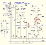
found 3 mistakes already (I think that's it) D4 reversed and wrong/mislabeled
servo caps. Fixed (below).
I don't know .. Carl , I might take a break ... refine/debug these 3 main amps -
(gnome/spooky/symasui).
PS- .asc for error hunting below , as well.
OS
servo caps. Fixed (below).
I don't know .. Carl , I might take a break ... refine/debug these 3 main amps -
(gnome/spooky/symasui).
PS- .asc for error hunting below , as well.
OS
Attachments
Last edited:
... I don't know .. Carl , I might take a break ... refine/debug these 3 main amps -
(gnome/spooky/symasui). OS
Ah come on, you know that you want to! It would round out your collection. Ha, ha ...
OS, please take a much deserved break and let us builders catch up with you.....😀
i wish that you can have a place somewhere where the latest and mightiest revisions can be seen, all in one place....
i wish that you can have a place somewhere where the latest and mightiest revisions can be seen, all in one place....
Waiting for this "whole package"Finally have it done ! 😱
(below 1/2) is the "pretty " PCB.
(below 3) is the schema it came from.
Went back to the standard symasym , more stable. Added the capacitive
shunts like the original .... they bring the THD harmonics right in line with the
original project. These are all optional , of course ... the IPS will run
perfectly with just one compensation cap.
But ... this amp "buries" the original in every other way. 😎
Will release the whole package after "proofing" 😱 .
OS

This is a work for this afternoon

Last edited:
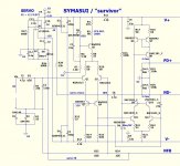
Well ... here it is !
(attached ) is the "package" (debugged).
Let me explain it. M. Bittners "symasym" uses the Otala style VAS (CM +
differential) with a simple LTP input pair ...
he then adds adds R/C shunt compensation to the VAS's output.
I simulated the original side by side with my design.
Cvs1/Cvs2 (below 1 schema) , reduces total closed loop gain and lowers the
UG. The "side effect" of this reduces H3/5/7 even more ... but increases
H2/4. My design can compensate by adding a small amount of lead
compensation (Clc ... 2.2-2.7pF) , thus allowing the reduction of Cdom (C7).
This increases the UG point and slew rate back to where we started.
Bittner used 100K/330pF for his shunts. My design has 5X the impedance
(cascode/wilson)and drives an EF3 .... 330K/47pF, accomplishes the same task.
In the end , I simulated the original and mine - both had the same FFT. Should
sound almost the same.
What is different , most of my devices can be low voltage ... except
for Q3-4 /Q8,9,10 (regulated front end). THD is 1/5th the symasym (5ppm) at
60V p-p and 20 at 120V.
It can also go where the symasym can't ... just like the spooky , 150V p-p
is EASY for this IPS @ 25ppm.
NOT the same hawksford VAS , Not a symmetrical design (despite the name).
This should have a totally different "character" than the balanced IPS's.
The FFT says so .
-Balanced = cancellation of H2 /4 ... even harmonics.
-unbalanced (this amp)= almost no H3/5/7 ... odds are gone.
PSRR is also -110db or better across the audio spectrum.
PS - Cvs1/2 and Clc are totally OPTIONAL. IPS will run happily on just C7 (33-47pF).
OS
Attachments

Last edited:

I have heard a lot of people talking about badly designed DC servos in audio circuits, does anyone know of a source of information on these problems, so I can get up to speed with everyone else?
I have heard a lot of people talking about badly designed DC servos in audio circuits, does anyone know of a source of information on these problems, so I can get up to speed with everyone else?
Who are "lots of people" ...and what servo ?
Most servo's I've seen are 30 years running. 😕
I would not use them if I thought they would fail ...
PS - they are just "bombed out' ... and are too scared to add some 21'st century additions.
50c chip don't scare me !
OS
Last edited:
Hi OS
How necessary is to put the servo in such topology if match well the LTP and VAS ?
can we put ksa1015=bc560 and ksa992 ksc1845 =2n5401-2n5551 ?
what is the substitutability transistor?
Nikos
How necessary is to put the servo in such topology if match well the LTP and VAS ?
can we put ksa1015=bc560 and ksa992 ksc1845 =2n5401-2n5551 ?
what is the substitutability transistor?
Nikos
Last edited:
Many years ago I had built the Titan 2000 with LTP diamond topology match very good without servo 5-10mv with servo 1-6mv offset , but the sound badly .
Attachments
Last edited:
Must be something wrong with servo. In my latest prototype I've got less that 0.1 mV offset and no influence on sound with servo.
Hi,
I assume that Keantoken rather referred to the sonic implication of servos and not the possibility of failure.
The typical first-order-filter inverting servo still puts out some signal at as high as 1kHz and above.
In a configuration like in #1624 its corrective voltage is fed as error signal into the most sensitive point of the amplifier.
Imho no wonder that it may influence on sonic character.
I see two possible solutions.
First is the use of more filtering, for example post LP-filtering the servo, to get rid of artefacts within the audible range.
Or second to find a less sensitive point to feed the error signal into.
This point could e.g be a source/emitter of a current source or current mirror.
jauu
Calvin
vzaichenko
The sound quality does not change with or without the servo.I m talking for Titan 2000.
The sound quality does not change with or without the servo.I m talking for Titan 2000.
Last edited:
Hi,
I assume that Keantoken rather referred to the sonic implication of servos and not the possibility of failure.
The typical first-order-filter inverting servo still puts out some signal at as high as 1kHz and above.
In a configuration like in #1624 its corrective voltage is fed as error signal into the most sensitive point of the amplifier.
Imho no wonder that it may influence on sonic character.
I see two possible solutions.
First is the use of more filtering, for example post LP-filtering the servo, to get rid of artefacts within the audible range.
Or second to find a less sensitive point to feed the error signal into.
This point could e.g be a source/emitter of a current source or current mirror.
jauu
Calvin
Interesting. I deliberately tried to see some artifacts at DC servo output in my CFA prototype (non-inverting servo). I fed a square wave through the amplifier, having about 20W output power @ 4ohm resistuve load. 100 Hz, 500 Hz, 1000 Hz. Nothing. Just very low level HF noise, not influenced by the signal.
I will run some tests at the lower end (around 20 Hz) over the weekend.
vzaichenko
The sound quality does not change with or without the servo.I m talking for Titan 2000.
Nikos, sorry, then I did not understand your initial post about Titan correctly.
Nikos, sorry, then I did not understand your initial post about Titan correctly.
Must be something wrong with servo. In my latest prototype I've got less that 0.1 mV offset and no influence on sound with servo.
No problem .
when you say 0.1 mV offset on prototype - which amp ?
and without servo - offset?
- Home
- Amplifiers
- Solid State
- Slewmaster - CFA vs. VFA "Rumble"