OS, a couple of thoughts on the OPS.
Is there any fundamental issue with placing the damping resistor for the output coil inside the coil? I'm looking to free up some space to see of it is possible to make room enough for 25mmø local capacitors but need some added real estate to do so. Such a change opens up capacitor choices, especially in the 100V range. I'm most interested in keeping things to a relatively low profile. Also any serious aversion to the Zobel resistor being placed vertically? Or maybe a split Zobel to reduce component footprint or allow placement flexibility?
Is there any fundamental issue with placing the damping resistor for the output coil inside the coil? I'm looking to free up some space to see of it is possible to make room enough for 25mmø local capacitors but need some added real estate to do so. Such a change opens up capacitor choices, especially in the 100V range. I'm most interested in keeping things to a relatively low profile. Also any serious aversion to the Zobel resistor being placed vertically? Or maybe a split Zobel to reduce component footprint or allow placement flexibility?
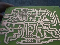
The first SYMASUI is here.
I hope a test is possible tomorrow.
I hope a test is possible tomorrow.
Attachments

Last edited:
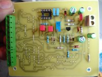
Hi Jason i see your work .Excellent work!Thimios, man, you are a machine!
Mine pcb are all home made, not so beautiful as yours.
Last edited:
Hi Thimios,
Looks very good. May I ask which method you are using for making your PCB's?
Thanks,
Mogens
Looks very good. May I ask which method you are using for making your PCB's?
Thanks,
Mogens
one benefit to using a servo is correction of dc offset due to thermals.
most (meaning "not all") amps posted as diy projects are not designed as true dc amplifiers. using discrete parts, it is expensive and hard to do correctly and successfully. the easy way around that is to use a correctly designed servo.
i'm not going to touch the question of why would you want a dc capable audio amp.
😉
mlloyd1
Hi OS
How necessary is to put the servo in such topology if match well the LTP and VAS ?
can we put ksa1015=bc560 and ksa992 ksc1845 =2n5401-2n5551 ?
what is the substitutability transistor?
Nikos
So you can play AC/DC of course! 😀
LOL. Oh my God, I can not hear DC signal. Am I normal? 😀
I think the purpose of servo is to replace trimpot adjustment of DC offset.
For home audio, servo for compensating DC offsett that cause by thermal is not necessary because we use it not for long time. May be it is useful for PA amp.
Except CFA with diamond buffer, it should use servo.
The purpose of the dc servo concept was to eliminate DC drift and offset when coupling/feedback caps were eliminated as a potential source of distortion; This is especially important when large cap values were needed for low Z circuits. The size and cost of a good film cap is also substantial... a lot more cost and size than an opamp and a couple RC's.
THx-RNMarsh
THx-RNMarsh
Last edited:
one benefit to using a servo is correction of dc offset due to thermals.
most (meaning "not all") amps posted as diy projects are not designed as true dc amplifiers. using discrete parts, it is expensive and hard to do correctly and successfully. the easy way around that is to use a correctly designed servo.
i'm not going to touch the question of why would you want a dc capable audio amp.
😉
mlloyd1
2 reasons I am now using servo's.
1- Lower LF thd than with a DC blocker cap.
2- the cost of the IC , and the 5 small caps is about the same as
a large 220u -470u NP electrolytic (plus a offset trimmer + 3 resistors)) .
The layout and design is more complicated , but the performance is
better from both a end user and a thermal standpoint.
OEM's use my servo ... both the accuphase and harmon/ kardon use
just about the same design - it's cheap , it works ....
PS - no matching , as well ... 😀
Edit , keep in mind ... my Z5900 sansui's Ne5532 dual servo is still
going strong after 32 years !!
OS
Last edited:
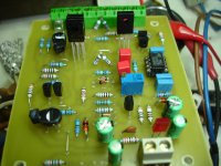
Thimios - important !!
C5's polarity is reversed ... positive goes to the regulated
12V rail.
It most likely would not of gone "poof" 😱 but C5 might of got hot.
CCS might not of worked (or low I) ....
Sorry . 😱
Another stinkin' lable error !!! argggg.
OS
C5's polarity is reversed ... positive goes to the regulated
12V rail.
It most likely would not of gone "poof" 😱 but C5 might of got hot.
CCS might not of worked (or low I) ....
Sorry . 😱
Another stinkin' lable error !!! argggg.
OS
LOL. Oh my God, I can not hear DC signal. Am I normal? 😀
I think the purpose of servo is to replace trimpot adjustment of DC offset.
For home audio, servo for compensating DC offsett that cause by thermal is not necessary because we use it not for long time. May be it is useful for PA amp.
Except CFA with diamond buffer, it should use servo.
It is important to understand, that servo is replacing not a trimpot, but a guy, sitting in front of it with a screwdriver, looking at the V-meter and adjusting it constantly 🙂 Trimpot is static, servo is dynamic.
My practical measurements show the following (same amp):
- DC servo off - output offset fluctuates slowly in the range +/- 70mV;
- DC servo on - output offset fluctuates in the range +/- 0.1mV.
BTW, why except CFA with diamond buffer?
The above example is actually the one with diamond buffer.
OS, a couple of thoughts on the OPS.
Is there any fundamental issue with placing the damping resistor for the output coil inside the coil? I'm looking to free up some space to see of it is possible to make room enough for 25mmø local capacitors but need some added real estate to do so. Such a change opens up capacitor choices, especially in the 100V range. I'm most interested in keeping things to a relatively low profile. Also any serious aversion to the Zobel resistor being placed vertically? Or maybe a split Zobel to reduce component footprint or allow placement flexibility?
Depending on what the resistor has in it, it might mess with the properties of the coil. Some materials can cause distortion.
A better method I know of is to locate the coil away from the board with a twisted wire pair. The parasitics of the pair are not enough to make any difference in behavior. What might make a difference however is if you increase the inductance of the resistor. So leave the resistor where it's at and place the coil somewhere else, maybe just raise it off the board an inch or so with stiff twisted wires.
JK , you could use a non-ferric / non- inductive resistor inside the
Coil. More expensive ... 🙁
Your concern is not enough capacitance for the main decouplers.
Consider this , if you use 47uf for all 5 pair OP decouplers ... plus use
just 220-330u for the main ones, you will end up with 500 -600uf
total.
If your PS is close to the amp - will it matter ? Those rail traces are
HUGE ... not much inductance or voltage drop here !
PS - a Nikko amp I repaired only had a single 22uF/100V at the rails
for each channel.
Depending on what the resistor has in it, it might mess with the properties of the coil. Some materials can cause distortion.
A better method I know of is to locate the coil away from the board with a twisted wire pair. The parasitics of the pair are not enough to make any difference in behavior. What might make a difference however is if you increase the inductance of the resistor. So leave the resistor where it's at and place the coil somewhere else, maybe just raise it off the board an inch or so with stiff twisted wires.
Absolutely. A good approach is to place the Zobel network on a separate small PCB close to the output terminals. As a last resort, one can mount 4 Zobel components right on the terminal pins 😉
Ok don't worry, mine mistake🙁C5's polarity is reversed ... positive goes to the regulated
12V rail.
It most likely would not of gone "poof" 😱 but C5 might of got hot.
CCS might not of worked (or low I) ....
Sorry . 😱
Another stinkin' lable error !!! argggg.
OS
It is important to understand, that servo is replacing not a trimpot, but a guy, sitting in front of it with a screwdriver, looking at the V-meter and adjusting it constantly 🙂 Trimpot is static, servo is dynamic.
My practical measurements show the following (same amp):
- DC servo off - output offset fluctuates slowly in the range +/- 70mV;
- DC servo on - output offset fluctuates in the range +/- 0.1mV.
BTW, why except CFA with diamond buffer?
The above example is actually the one with diamond buffer.
I gave that analogy once. 😀
My "Badger amp" will go from +2mv to -2 mv depending on time of day
... the weather ...etc. 😀
My Sansui servo'ed amp will be at .5mv ALWAYS ... .5mv for 32 years 😎
Concerning "servo leakage" .... the small amount of HF that passes through
the servo just adds to the total NFB signal. The difference in phase (op-amp vs. main)
between the "leakage" and the main feedback signal changes the total
margin and CLG (VERY , very slightly). Since the "leakage" and
the main NFB are exactly the same signal ... no added THD , in fact ..
LESS at low frequencies.
OS
Last edited:
Ok don't worry, mine mistake🙁
NO , my friend .... all my fault. I originally decoupled the LED CCS to ground,
found PSRR was much better decoupling to the 12V rail ... failed
to update the PCB . 🙁
OS
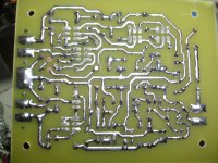
Thanks ,please look here.http://www.diyaudio.com/forums/solid-state/221741-dx-blame-st-together-dx-super-116.htmlHi Thimios,
Looks very good. May I ask which method you are using for making your PCB's?
Thanks,
Mogens
post#1152. If you have any question please ask again.
Thimios.
Last edited:
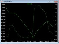
Thimios .... tips !
So you get the very best listening impressions.
C7 = 33p
Clc= 2.7p
Cvs1/2 = 47p
don't make Clc too big .. like 5p (peaking) .. better to be small (2pF)
(below) is the ideal bode with the values above. A VERY
well behaved amp (stability wise)
PS - you can bring this amps unity gain up over 2mhz and it will
still be "well behaved". 😎
(C7 = 22p Clc= 3.3p - 2.1mhz UG)
You can also reduce R9/R10 to 33R for 72db CLG with still ... plenty of
margin .... VERY wide range while being very stable. 🙂
The only way to get any ringing on SW was to go (C7 = <15p) or
to use a forbidden 10p+ for Clc ....
PS - this amps psrr is 20db better than the symasym , as well (below 2). (better than the
blameless ,too)
OS
Attachments

Last edited:
- Home
- Amplifiers
- Solid State
- Slewmaster - CFA vs. VFA "Rumble"