My curiosity is in-between. I'd like to see a few more parts, such as enough for about 8W to 8R and some kind of baker clamp or other clipping mitigation. This might be a fun flea power project for desktop use (at point blank range).
Hello , dan !!
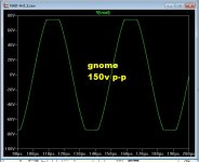
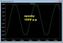
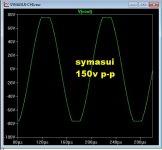
These amps don't saturate/stick and misbehave on clip (don't need no stinkin' clamps). 😀
(below 1 , 2 , 3) Gnome - spooky - symasui ... (85V all)
40ppm , 20ppm , sym is at 6ppm (125Vp-p) !! 😎
"gnome" would be an easy headphone amp at +/- 12V 😎 .
Clip away.
PS - this would be your "max headroom" with 85v rails .. BTW.
OS
Attachments
OS,
If you used the Gnome for a headphone amp would you strip out the servo circuit and leave the nfb loop or remove that also?
If you used the Gnome for a headphone amp would you strip out the servo circuit and leave the nfb loop or remove that also?
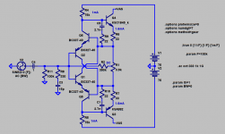
Here's a version for higher voltage rails and better compensation. You may have already done it mostly, but this compensation should work better. Also shown is decoupling/comp wiring for best stability.
The drawback of this compensation is that the input RC gets bigger. This RC is needed for stability with inductive sources, so worry about it only at the end when you start to test with source impedances higher than 50 ohms.
The drawback of this compensation is that the input RC gets bigger. This RC is needed for stability with inductive sources, so worry about it only at the end when you start to test with source impedances higher than 50 ohms.
Last edited by a moderator:
Okay, that last schematic was very wrong. Let me try that again. Sorry for any confusion. Here are schematics with both compensation methods, in case one doesn't work. I prefer the first in terms of numbers. They are both for 75V rails.
Attachments
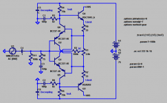
The bases of Q5 and Q6 are the NFB points.
How does that work without shorting them together?
Hi Os!Hello , dan !! These amps don't saturate/stick and misbehave on clip (don't need no stinkin' clamps). 😀
(below 1 , 2 , 3) Gnome - spooky - symasui ... (85V all)
40ppm , 20ppm , sym is at 6ppm (125Vp-p) !! 😎
"gnome" would be an easy headphone amp at +/- 12V 😎 .
Clip away.
PS - this would be your "max headroom" with 85v rails .. BTW.
OS
Those are neat new amplifiers there! But 85v rails would blow my desktop speakers straight off the desk. 😀 Hey, I got plenty of loud stuff. I'm actually "shopping" for a very small amp with pretty much a Class A small signal voltage amp run on nested regs and in global negative feedback with a Class aB large current buffer.
Daniel,
If you like Kean's circuit why not just add a driver and small output stage? Wouldn't take much to drive 8watts at 8 ohms with a small output device. Not much more than a large headphone amp really. Or just use a 3886 chip amp, that would be in the sweet spot for that chip.
If you like Kean's circuit why not just add a driver and small output stage? Wouldn't take much to drive 8watts at 8 ohms with a small output device. Not much more than a large headphone amp really. Or just use a 3886 chip amp, that would be in the sweet spot for that chip.
Thinking too much maybe...
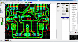
Got to thinking about the availability of the specified component values for running the Monster at HV rails, meaning 100V capacitors. I couldn't find much available in a 12.5mm can for the 470µF cap for the CM. I have pushed and pulled a little to allow for 16mmø 7.5mm LS caps there. Any thoughts?
Got to thinking about the availability of the specified component values for running the Monster at HV rails, meaning 100V capacitors. I couldn't find much available in a 12.5mm can for the 470µF cap for the CM. I have pushed and pulled a little to allow for 16mmø 7.5mm LS caps there. Any thoughts?
Attachments
How does that work without shorting them together?
Like this:
http://www.diyaudio.com/forums/solid-state/248105-slewmaster-cfa-vs-vfa-rumble.html#post3878954
I'm not sure where to find that schematic, but you should use the feedback resistors that are already on the amp.
Question; How high?
Answer; High enough.
The amp in this schematic
http://www.diyaudio.com/forums/solid-state/248105-slewmaster-cfa-vs-vfa-rumble-32.html#post3878954
shows the values for everything except the FB resistors.
Answer; High enough.
The amp in this schematic
http://www.diyaudio.com/forums/solid-state/248105-slewmaster-cfa-vs-vfa-rumble-32.html#post3878954
shows the values for everything except the FB resistors.
Question; How high?
Answer; High enough.
The amp in this schematic
http://www.diyaudio.com/forums/solid-state/248105-slewmaster-cfa-vs-vfa-rumble-32.html#post3878954
shows the values for everything except the FB resistors.
On both the gnome (cfa) ,and symasui (vfa) ... increasing the gain does
2 things - lowers the unity gain point / slew rate and increases THD.
I simulated 20X to 40X gains ... all you have to do is
lower the compensation cap value proportionally-(with higher gain}.
Another way around the slight loss in performance is to use lower value
resistances in the proportion you choose (more FB current). This
especially makes a difference in the CFA !
PS - FB resistors are on the IPS's .... most are 28X gain.
OS
- Home
- Amplifiers
- Solid State
- Slewmaster - CFA vs. VFA "Rumble"