But IMHO, the biggest unsimmed evil in most PA designs is the length of cable/track from the amp to the big PSU caps. I've simmed this extensively in the last Millenium with my home brewed linear circuit analyzer .. and even more important .. tested & confirmed the findings in 'real life'.
Sounds particularly interesting to me as a PSRR (rather than THD) geek
")
Did you look at how this particular effect relates to aforementioned PSRR at higher frequencies via base-collector (or gate-drain) capacitance?
ISTM if you have any results they should be fed into Waly's analysis for the optimum number of output devices.
As my home brewed circuit analyzer was Linear it could only investigate stability, response & PSR. No THDSounds particularly interesting to me as a PSRR (rather than THD) geek
Did you look at how this particular effect relates to aforementioned PSRR at higher frequencies via base-collector (or gate-drain) capacitance?
ISTM if you have any results they should be fed into Waly's analysis for the optimum number of output devices.
Yes I did look at the effect of evil Ccb but the most 'important' PSR route was the compensation topology. That's why I prefer simple 'pure Cherry' as in tpc-vs-tmc-vs-pure-cherry instead of more complex versions (eg 2 pole Cherry) I've tried cos the 'pure Cherry' allows substantial improvement of PSR by adding a single NPO cap.
Waz is ISTM?
...in practice, we need to take both approaches.
For the first approach, we also need to identify the most important stuff that is not simulated...
Of course, part of the reason to simulate is to find out what is the most important stuff.
Then we can maximise our efforts into the areas that yield the best improvements.
IMHO, you need to have OPS as close as possible to the VAS; ie no ribbon cables etc especially if you intend advanced comp. like TMC or 'pure Cherry'.
This is obviously desirable from first principles.
I know you blamed it for much of your trouble with simulation of Toni's amp but I don't have a feel for its sensitivity yet.
I would be curious to learn what is the weak link.
Trace inductance? Stray capacitance?
... unsimmed evil in most PA designs is the length of cable/track from the amp to the big PSU caps[/B]. I've simmed this extensively in the last Millenium with my home brewed linear circuit analyzer .. and even more important .. tested & confirmed the findings in 'real life'.
Yes. I have not yet simmed this but reliable people consistently report this as a critical area.
While you can and should get the OPS close to the VAS in practice, its much more difficult to move the PSU within a cm of the power amp.
Since this is known to be sensitive, I have spent some time on this.
Power supply capacitors directly under the OPS and a soft iron EM screen/shield so they can be as close as possible but without noise.
Surface mount bypass capacitors on the board.
I think I can do better than the typical, casual power supply layout with too much wire.
You have any ideas on this?
Best wishes
David
The weak link was the ribbon cable. Though Toni maintained that it was of no consequence .. for the sims, simulating the ribbon cable was essential to show some of the effects he found.I know you blamed it for much of your trouble with simulation of Toni's amp but I don't have a feel for its sensitivity yet.
I would be curious to learn what is the weak link.
Trace inductance? Stray capacitance?
To get SPICE and 'real world' closer would have require drastic revisions to his PCB(s) and physical layout. ie a single PCB with VAS & OPS close together. Too many possible trace inductances & capacitances on his present complicated layout for me to pontificate.
FWIW, it was the ground track on the ribbon which was important. The others, including the leads from VAS collector to OPS were relatively problem free, with or without distributed capactiance to go with the inductance.
But I did learn a lot about what affects this and how to make it more robust in future.
My motive for spending so much time with the design was trying to get more 'real life' confirmation of SPICE stuff. Unless these move closer together, any SPICE work needs to be taken with a large pinch of salt.
The most important finding from my Jurassic work was that the important caps are power rail Electrolytics in close proximity to the OPS & VAS.Since this is known to be sensitive, I have spent some time on this.
Power supply capacitors directly under the OPS and a soft iron EM screen/shield so they can be as close as possible but without noise.
Surface mount bypass capacitors on the board.
I think I can do better than the typical, casual power supply layout with too much wire.
You have any ideas on this?
Electrolytics cos damping is vital and their ESR is almost ideal for this. ie bigger caps need smaller ESR.
These need to decouple to a Dirty Earth that goes back to the Star Point via the same route as the Power Rails. Toni re-routed one of his decoupling caps on my recommendation and got better results.
A caveat for close Electrolytics is that they are very close to the hot OPS.
Today, with nice small high value ceramics, it might be better to have 1u ceramics with small resistors in series.
But another advantage of the close Electrolytics is that they give better THD20k but again at the expense of getting hot.
Rail to Rail Electrolytics help with THD20 but not with stability.
_____________________
BTW, this finding holds for small signal stuff with regulated rails too. See from #41 of http://www.groupdiy.com/index.php?topic=37307.80
Last edited:
FWIW, it was the ground track on the ribbon which was important.
Coupled via the track resistance or inductance?
The most important finding from my Jurassic work was that the important caps are power rail Electrolytics in close proximity to the OPS & VAS.
Electrolytics cos damping is vital and their ESR is almost ideal for this. ie bigger caps need smaller ESR.
I should have stated that I plan 10,000 uF main power supply electrolytics, paralleled one per OPS transistor.
Then on-board SMD electrolytics probably around 100 uF, also one per OPS transistor.
Plus any extra bypass if needed, this I don't know about yet.
These need to decouple to a Dirty Earth that goes back to the Star Point via the same route as the Power Rails.
Yes, had already worked this out for inductance/ stray field reasons.
Seems obvious but nice to have it checked.
A caveat for close Electrolytics is that they are very close to the hot OPS.
Hi temp. here for sure. 105 C presumably.
Today, with nice small high value ceramics, it might be better to have 1u ceramics with small resistors in series.
Have seen at least one study of capacitors in parallel where they didn't behave as one would naively expect.
But 1 uF next to the 100 uF electrolytic seems plausible. Any advice on that?
Best wishes
David
The most important finding from my Jurassic work was that the important caps are power rail Electrolytics in close proximity to the OPS & VAS.
Electrolytics cos damping is vital and their ESR is almost ideal for this. ie bigger caps need smaller ESR.
These need to decouple to a Dirty Earth that goes back to the Star Point via the same route as the Power Rails. Toni re-routed one of his decoupling caps on my recommendation and got better results.
A caveat for close Electrolytics is that they are very close to the hot OPS.
Today, with nice small high value ceramics, it might be better to have 1u ceramics with small resistors in series.
But another advantage of the close Electrolytics is that they give better THD20k but again at the expense of getting hot.
Rail to Rail Electrolytics help with THD20 but not with stability.
_____________________
BTW, this finding holds for small signal stuff with regulated rails too. See from #41 of http://www.groupdiy.com/index.php?topic=37307.80
Maybe good idea is to have a cap multipliers for the OPS on the same board.
Look here http://www.diyaudio.com/forums/solid-state/216780-tt-amp-200w-8ohm-701w-2ohm.html
and here complete schematic http://www.diyaudio.com/forums/solid-state/216780-tt-amp-200w-8ohm-701w-2ohm-2.html#post3115503
Id did not build it and no experience from real life, no time to buld all those amps.
BR Damir
FWIW, it was the ground track on the (astx's) ribbon which was important.
Inductance. The resistance is handled by the Clean / Dirty Earth scheme to his Star Point. Clean is coupled to the i/p sockets and then to his Star. THD is good.Coupled via the track resistance or inductance?
But the inductance of such long leads affects stability in very subtle ways.
With loadsa electrolytics as you described, I've never found an improvement in either stability or THD on Power Amps or small signal OPA stuff with extra films or ceramics. ie I don't think extra bypass is required except for Golden Pinnae reasons.I should have stated that I plan 10,000 uF main power supply electrolytics, paralleled one per OPS transistor.
Then on-board SMD electrolytics probably around 100 uF, also one per OPS transistor.
Plus any extra bypass if needed, this I don't know about yet.
My suggestion of large ceramics with small series resistance isn't in parallel with the electrolytics. Its a possible high temperature replacement.Have seen at least one study of capacitors in parallel where they didn't behave as one would naively expect.
But 1 uF next to the 100 uF electrolytic seems plausible. Any advice on that?
The cheapo electrolytics will always give more capacitance (with the correct amount of resistance supplied by their ESR) in the smallest package which allows the closest proximity to the VAS & OPS so better stability & THD20. But they will dry out in that hot position.
The main consideration is size .. small enough to get close. You don't want to parallel cos that takes up more space.
Both ceramics & electrolytics have improved a lot since the early 90's though you have to be careful you don't run foul of fake electrolytics which don't last 12 mths. in computers.
But another advantage of the close Electrolytics [/URL]
yes, put them as close as possible.
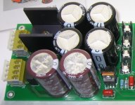
Attachments
Pavel, I meant they have to be close to the OPS & VASyes, put them as close as possible.
Thought I have shown several times that the length of the ribbon cable has only a capacitive influence on the amp. A longer ribbon cable bettered the stability because the higher capacitance to ground has added some sort of VAS compensation (today I know that this slightly bettered the gain margin - see post #701 - The effect of too less gain margin). All ground wires over the ribbon cable where dirty ground. Clean ground never has been routed to output stage via ribbon cable!The weak link was the ribbon cable. Though Toni maintained that it was of no consequence .. for the sims, simulating the ribbon cable was essential to show some of the effects he found.
To get SPICE and 'real world' closer would have require drastic revisions to his PCB(s) and physical layout. ie a single PCB with VAS & OPS close together. Too many possible trace inductances & capacitances on his present complicated layout for me to pontificate.
FWIW, it was the ground track on the ribbon which was important. The others, including the leads from VAS collector to OPS were relatively problem free, with or without distributed capactiance to go with the inductance.
...
BTW the real world amplifier uses TMC compensation and is pretty stable playing fine every day.
Think if you would recalculate the cherry compensation on the latest of my simulations (adding 2x28pF from VAS output to ground) and design it for a GM > 10dB and a PM > 60 dB maybe cherry compensation will work too. PM me if you want pcb samples.
Yes I have re-routed 2 pieces of 0.1µF caps from clean ground to dirty ground (via ribbon cable to output stage)....
Electrolytics cos damping is vital and their ESR is almost ideal for this. ie bigger caps need smaller ESR.
These need to decouple to a Dirty Earth that goes back to the Star Point via the same route as the Power Rails. Toni re-routed one of his decoupling caps on my recommendation and got better results.
...
But the most important re-routing may have been the collector of one of the VAS transistors from clean to dirty ground.
IMHO: to put the sensitive input/VAS stage away from all those big currents is better for those big amplifiers to get best THD and Noise values!
BR, Toni
Toni, I wasn't criticising your design. As I have said many times, it is excellent.Thought I have shown several times that the length of the ribbon cable has only a capacitive influence on the amp. A longer ribbon cable bettered the stability because the higher capacitance to ground has added some sort of VAS compensation (today I know that this slightly bettered the gain margin - see post #701 - The effect of too less gain margin). All ground wires over the ribbon cable where dirty ground. Clean ground never has been routed to output stage via ribbon cable!
BTW the real world amplifier uses TMC compensation and is pretty stable playing fine every day.
Think if you would recalculate the cherry compensation on the latest of my simulations (adding 2x28pF from VAS output to ground) and design it for a GM > 10dB and a PM > 60 dB maybe cherry compensation will work too. PM me if you want pcb samples.
What I was referring to is that once we got to a certain stage, the sims no longer reflected your 'real world' results.
eg simulating the higher capacitance on the ribbon didn't make this closer to 'real world'
Once the sim no longer reflects 'real world' you have to be very careful to make predictions based on it. In the early days of the thread I suggested some Cherry mods which proved good. Your 'real life' results were in line with the sims.
But as the performance level rose, this was no longer the case.
After simulating the ribbon with some success, I couldn't go any further without asking for even greater physical topology revisions. So I stopped.
There's no point my suggesting more Cherry compensation ideas until I get my sim to reflect your latest results.
My main reason for participating in your thread was to get some 'real life' confirmation of SPICE world Cherry sims. My thanks for being so patient with me and indulging some of my crazy ideas.
I learnt a lot from the exercise including what NOT to do. Also, this was my really big learning experience with TMC.
Yes. That was the important one.Yes I have re-routed 2 pieces of 0.1µF caps from clean ground to dirty ground (via ribbon cable to output stage).
But the most important re-routing may have been the collector of one of the VAS transistors from clean to dirty ground.
Coupled via the track resistance or inductance?
I should have stated that I plan 10,000 uF main power supply electrolytics, paralleled one per OPS transistor.
Then on-board SMD electrolytics probably around 100 uF, also one per OPS transistor.
Plus any extra bypass if needed, this I don't know about yet.
Yes, had already worked this out for inductance/ stray field reasons.
Seems obvious but nice to have it checked.
Hi temp. here for sure. 105 C presumably.
Have seen at least one study of capacitors in parallel where they didn't behave as one would naively expect.
But 1 uF next to the 100 uF electrolytic seems plausible. Any advice on that?
Best wishes
David
Hi David,
I always like to put about 1000uF per rail on the amp board close to the output transistors. If one does this, the wiring length to the big PSU reservoir caps does not matter much. These should of course be bypassed with iuF or so. These caps pretty much take care of the HF issues, making the arrangement far less dependent on the wiring to the PSU for distortion, etc.
An interesting half-crazy idea is to go far non-conventional when one does this, not using big wires to the PSU, but rather small-tightly coupled ones, including ground. The little bit of resistance may actually help matters and even give a little additional filtering from the PS at HF. Consider shielded microphone cable, wiring the rails on the inside wires and using the shield as the ground return to the PSU reservoir caps. When doing this, I return the speaker output to the amp board at the center of the on-board caps rather than a star ground at the PSU when I do this.
I realize that Self does not recommend twisting together the two rail leads and the ground, instead preferring to twist together only the two rail wires.
I always prototype with relatively long wires to the PSU.
Cheers,
Bob
Local or on-board cap/regulator is always the best approach.
The main filter/energy storage caps can be mounted with the terminals facing downward so they are close to the chassis and the PS and return wiring run against the chassis. Ground the caps' metal case also, if it has one, to the chassis via the hold-down mounting hardware. if mounted in the typical way with terminals facing upward, run the PS wires to it against the chassis and close up against the sides of the grounded cap case.
-Thx-RNMarsh
Last edited:
This isn't crazy at all. The limit is Cherry's A New Distortion Mechanism in Class B Amplifiers where he puts series inductance in the PSU leads with large local electrolytics.An interesting half-crazy idea is to go far non-conventional when one does this, not using big wires to the PSU, but rather small-tightly coupled ones, including ground. The little bit of resistance may actually help matters and even give a little additional filtering from the PS at HF.
I don't think its necessary to go to his lengths (the inductors) but this was the paper that refined my thinking on the subject.
He does this on his ETI NDFL amp that is on jan.didden's website. Loadsa useful practical details therein.
In da old days, it was difficult to find good caps small enough to put near the OPS & VAS. 220u was the biggest I could squeeze in. I remember marvelling at some really supa dupa full power THD20k measurements on a 50W prototype .. until the local caps blew up.
Last edited:
Just buy some opamps then use your headphones. You could see their characteristics through their sheets. If you don't accept 0.01% thd is unhearable, then do the test, may be you could hear additional 0.01% signal added to 100% signal, then just show me the way to do the test.Which ones have you tried and what did you hear that's not neutral & natural?
I don't see how mentioning the brand can change its neutrality & naturalness
You have a strange way to see the things ;-)
What else than 'distortions' can modify the "sound of a signal" and make an amplifier not 'transparent' ?
An other what ?
Yes it is better called as "another things", it will stay simple with that.
Sorry for late replay, I have problem with my switching AC regulator, the mosfet hit the limiter at certain loads.
Bob C........An interesting half-crazy idea is to go far non-conventional when one does this, not using big wires to the PSU, but rather small-tightly coupled ones, including ground. The little bit of resistance may actually help matters and even give a little additional filtering from the PS at HF. ............
I give you permission to promote my half-crazy idea.
It works.
Most of them are added (predicted or measured) modulating error to the output(like wavebourn did, also that jfet), and adding measured error back to the input(like bob Cordell did).What is a basic topology for cancellation and what variations exist? We can cover what others have done to help get the creative juices flowing but would like some fresh ideas as well.
Thx-RNMarsh
/OT
This is a funny remark for several reasons:
1. Why would a 'harmonic mean rule' be much nicer than a 'product rule'?
2. Contrary to what the LT1166 datasheet says, this chip does keep the minimum OP current at about half the quiescent current (see: Comparison of a few techniques).
3. Marcel's version of the auto-bias circuit (see: ‘Audio power with a new loop’, EW, Feb. 1996, pp.140-143),
behaves more or less the same as the LT1166.
Cheers, E.
Hi Edmond,
I never actually used the LT1166, my comments are based on the information I read about it when it was introduced. If Linear Technology implemented a harmonic mean rule or something similar in the LT1166 but state in its data sheet that they used a product rule, then what I've written is clearly not valid (and Linear Technology then obviously has an internal communication problem).
In the literature you see that many authors prefer non-switching output stages, that is, output stages where the current through one output device approaches some nonzero value (like half the quiescent current) when the current through the other gets large. The supposed advantage is that the inactive device can turn on quickly when it is already biased at a reasonable current rather than switched off entirely or almost entirely. This behaviour is easy to achieve with a class AB control loop by choosing a control rule that lets the current through one device approach some nonzero minimum value when the current through the other output device tends to infinity.
I don't know what effect this has on the distortion measured with sine waves or with actual music, I never compared the distortion of otherwise similar amplifiers with exp(-I1*R)+exp(-I2*R), harmonic mean and product control rules.
By the way, I like the fact that you put a Dutch quote below your posts.
Best regards,
Marcel
- Home
- Amplifiers
- Solid State
- CFA Topology Audio Amplifiers