OK, I assume you realise that that a coil "on" or across the output terminals is virtually a short to DC and low audio frequencies. That won't work so presumably you mean in series with the + lead, so you have an output coil, but it's located at the terminals rather than than on the PCB. That's fine but a damped inductance isn't very effective as a normal low pass filter so the R, L values might need some juggling to improve it.What I actually mean is to connect a coil with a 10R resistor in parrallel on the output.
A low-pass filter network would probably need to roll off with a 3dB down point above 200kHz and you can use that to calculate L for a simple LR filter. More often, manufacturers adding some RF protection to a power amplifier just fit a second RC zobel across the output terminals with about 10% of the capacitance of that used in the power amplifier itself. i.e. 10nF rather than 100nF but also using a good quality, high voltage film type. That's simple and what I would try first.
It won't be much fun testing a cure unless you have a problem but you could operate a 2-way radio near the amplifier and see if that breaks through.
Wrong compensation caps
Finished the other board and installed 1nf compensation caps i.s.o 100pf. The 101 and 104 looked so similar in the workshop . When I put it on the scope I found that the sine wave did not look good, triangle looked bad and square wave looked like a triangle. On inspection I found the fault, but I did not listen to the amp on a speaker. Now I wonder, would you have heard something was wrong without having the board on a scope ? Lots of people build without testing afterwards on a scope, would they know If there were a problem ?. I saw on the scope when I touched the input that the output went insane high.
Finished the other board and installed 1nf compensation caps i.s.o 100pf. The 101 and 104 looked so similar in the workshop . When I put it on the scope I found that the sine wave did not look good, triangle looked bad and square wave looked like a triangle. On inspection I found the fault, but I did not listen to the amp on a speaker. Now I wonder, would you have heard something was wrong without having the board on a scope ? Lots of people build without testing afterwards on a scope, would they know If there were a problem ?. I saw on the scope when I touched the input that the output went insane high.
With a critical error like using a compensation capacitor that is 10X the correct value, you can't expect the amplifier to work properly at all. Playing audio through the amplifier would be no less obvious in showing you that something big is wrong but of course, we need visual aids when we don't have enough experience with the device to recognize what a likely cause is.
Question: Did you recognize just what was wrong when the oscilloscope trace seemed so wrong?
I suspect that you probably still had to look for the cause, just as we would by listening.
I like using 'scopes and analysing faults for the fun of it and I admit to making some bad mistakes when replacing components myself. I've used a scope to confirm a fix but it didn't pinpoint the fault location.
I once bought an amplifier from a guy who was a retired engineer and assumed it was fine. Long story short, it made wierd motorboating noises and on return, the guy looked inside, found a stray wire and simply cut it, closed up and connected it to his audio system to demonstrate - It sounded just great. He apologised for not being more careful with removing an experimental circuit. It has been working for me and others I loan it to, for 12 years now.
Ian, there were no problem setting the bias and DC offset were 12mv, so I did not expect something wrong, only that I got 6mv ac on the output with shorted input, after fixing that dc offset is 4mv and ac is 0mv. When touching the input wires with the wrong components I saw the scope go mad and then I suspected oscillation and something wrong.
I recall that -ve clipping level varied a few percent between different builds of older P3A versions but just how much different are your clipping voltages?
As P3A has a bootstrapped capacitor VAS, the actual negative signal peak voltage can depend on the supply voltage, voltage divider R9, R10 and C5. It's also possible to have the output of the VAS overshoot the rail voltage by adjusting that voltage divider enough, as it is in Mosfet applications where a higher drive than the rail voltage is necessary to get efficient use of the power supply.
I can't recall how much the actual negative clipping level is affected by the peak voltage level, but it may be worth adjusting the divider a little and retesting. Rod discusses the bootstrap design in the P3A and amplifier design articles but doesn't give any rules or clue to altering it in this way.
Sweet sounding wee nipper !!
Nice build Vrystaat...well done!
Stick to the reccommended component values and all is well.
P3A does not want altering its components..it may work but
not for long.
Regards,
Albert
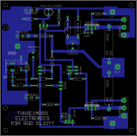
Hi everyone, I hope you are well, I attached my P3A design, I did it in size 100mm * 100mm since the heatsink (zd 2k model) makes me force the power transistors to be placed at that distance, the bd140 I left it in that position since it has a heatsink when using it in a voltage higher than 35 volts, and the PCB manufacturers (in China, some) have the offer of up to 2 sides for 5 dollars or less for this maximum size, personally, I like it the design achieved since I had no bridge left, although the fuses are absent, I would be placing them after the source capacitors.
Attachments
Read the P3a design and construction article at the ESP website: 60-80W Power Amplifier. Note that bias level has much to do with sound quality and hence the cooling requirements when running at the maximum power limit for the transistors. Unless you like your chances with a hot amplifier at max. power and you have a large heatsink, stay with a nominal 25+25VAC transformer and +/-35V DC rails.How maximum dc volts cab it be bear.please tell me.thanks
Hi sir
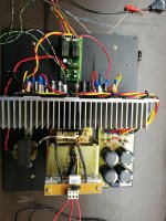
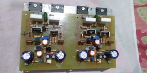
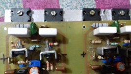
I completed two channel .power supply is 30..0..30 volts AC @3Ampre .sound is good but my output transistors become hot within two three minutes.I used heavy heatsink also.please suggest remedy.thanks
I completed two channel .power supply is 30..0..30 volts AC @3Ampre .sound is good but my output transistors become hot within two three minutes.I used heavy heatsink also.please suggest remedy.thanks
Attachments
Last edited:
Masood, I cannot see the heatsink but you seem to have attached the transistors directly to a strip of metal that does not seem perfectly flat and I cannot see any insulators or thermal grease to aid heat transfer. This is important for proper assembly of all power semiconductors with their heatsinks.
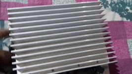
Perhaps I just can't see these details in your pic but you need to be specific and use correct heatsink materials to make the assembly work correctly at a safe working temperature. Is the metal sheet I can see the heatsink? Is it aluminium? Just how big is the heatsink and what fins does it have?
Even at just +/-30V DC supply, there will be a lot more heat with the recommended 70mA bias current than a more usual 15 mA bias setting that might normally be used with this CFP type of output stage.
To have both amplifiers coupled to a single heatsink, you need a heatsink rated ated at about 0.8 K/W or twice that if you use 2 separate heatsinks. All mating surfaces need to be perfectly flat and smooth, and a continuous film of white thermal grease should be applied to both sides of a thin mica washer sandwiched correctly between the power transistors and the heatsink. The single mounting bolt is not really adequate to apply sufficient even pressure to rubber pad (silpad) type washers and I suggest you use very thin mica instead, for best results.
As indication of a suitable size heatsink, a P3A I checked about 1 year ago was fitted a heavy piece of extrusion that had 15 fins and was 40MM thick, 75 mm high and 175 mm wide. With 70 mA bias current through both channels and 35V power supplies, the temperature settled at 52C on a day that was 28C. Even that feels quite hot to touch.
You could of course, just adjust the bias to a more normal current of just 10-15 mA (each amplifier) though that probably won't sound as good as the recommended setting.
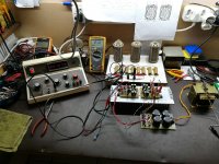
Finished with the electronic side, now to build into a nice Zebra wood chassis with oldskool Sifam round VU meters. Very happy with the sound as well !!
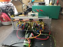
Rail distribution in general is wrong practice
cables as short is possible
if twisted then ground is supposed to be out of the twist
It could be nicer to have same length of cables for each ch .
Last edited:
Hi everyone, I hope you are well, I attached my P3A design, I did it in size 100mm * 100mm since the heatsink (zd 2k model) makes me force the power transistors to be placed at that distance, the bd140 I left it in that position since it has a heatsink when using it in a voltage higher than 35 volts, and the PCB manufacturers (in China, some) have the offer of up to 2 sides for 5 dollars or less for this maximum size, personally, I like it the design achieved since I had no bridge left, although the fuses are absent, I would be placing them after the source capacitors.
The amplifier will forgive most of the mistakes you made on the pcb design and play music after
point is that most amplifier will play with a bad pcb
if the target though is better stability and higher sound quality then you need to observe and study some pcb rules when it comes to audio applications.
Dear IAN is always nice to see you and still so nice to see you active on threads
I am actually busy beyond any expectation so its nice that i see that you keep up with some of my work and providing endless support to P3A friends
Thank you
Last edited:
- Home
- Amplifiers
- Solid State
- Rod Elliot P3A Layout - Critics