Yes,you don't need ground loops,MarianB has already explained this.😉like this?
Last edited:
Hey man, that beautiful layout is from Abetir (De Ocampo).😉
regards
Prasi
Hello Prasi,
As I am busy fixing my desktop I am attaching here the .lay files of my P3A lay out (Sprint Layout). Luckily my back up files still exists at 4shared.com. Anyone wanting to make a rework of my lay-out the file is free to had.
Regards,
Albert
PS. I am quoting from this earlier post of yours because I can' t view the later posts after post #350 by Ripcord. I read your post via email notification.
Attachments
I am attaching here the .lay files of my P3A layout (Sprint Layout).
Hello de ocampo
your P3A layout is very good, what is its size. And Can you have All macros used in this P3A layout during make in sprint layout, can you send me or give me a link where you get those macros.Thanks.
Last edited by a moderator:
sanbadgujar,
Thank you, unfortunately I can no longer find my makros back-up. You could copy the components in the layout and save as makros to the program library.
Regards,
Albert
Thank you, unfortunately I can no longer find my makros back-up. You could copy the components in the layout and save as makros to the program library.
Regards,
Albert
 sanbadgujar, and all, do not post your email address here, do it thru pm's..
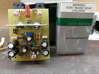
Sweet sounding wee nipper !!😀
It looks good 🙂 So which transistors did you use for your build?
I have used BD35/36C as outputs. BC546 and BD139/140. Sakis I have read somewhere that the led must be close to the transistor and on the pbc that I have used they are next to each other, that's why I thermo coupled them. If its wrong is easy to remove the heatshrink.
Would there be any negative effect when connecting a coil and a parallel resistor on the binding posts to counter for RF problems ?
Would there be any negative effect when connecting a coil and a parallel resistor on the binding posts to counter for RF problems ?
What is the source of the RF and how is it affecting the amplifier?
Can the amplifier be located away from the RF source? Can the RF be suppressed at source?
If the interference is severe and the frequencies and source of the RF have been determined:
RF filters are normally designed to filter specific frequencies or bands of frequencies. A typical low-pass filter might be a coil followed by a capacitor shunt to ground or several of these combinations, depending on the attenuation needed and frequencies involved. Other types of RF filters could be considered, such as passing affected leads using a few turns through a ferrite toroid core.
I think a Zobel (RC series combo) would be more appropriate for RF bypass filtering of the speaker leads. That's the type of filter normally used there, with values appropriate to RF rather than audio frequencies.
A parallel coil/resistor at the output is a heavily damped filter to kill interaction, known as ringing, between the loudspeaker and the output stage. This usually shows up at supersonic, as in >20 kHz, rather than RF frequencies, where most concern nowadays is about the MHz to GHz or digital transmission and spurious emissions range.
A parallel coil/resistor at the output is a heavily damped filter to kill interaction, known as ringing, between the loudspeaker and the output stage. This usually shows up at supersonic, as in >20 kHz, rather than RF frequencies, where most concern nowadays is about the MHz to GHz or digital transmission and spurious emissions range.
I read "RF problems" as interference as opposed to ringing. It could be ringing is more the issue as you describe.
Hi currentflow, I think you have rightly focused on the RF source and ways to attenuate it, though I read the post as concern for the possibility rather than than any existing problem. I suspected that the missing output coil may have gotten into the mix of ideas somewhere and we seldom see its function explained anyway.
An output coil isn't necessary with P3A but adding something similar for RF blocking, wouldn't work very well because of the low-Q audio circuit applied to high RF impedances. There is a plan here but I think it would be simpler to try capacitive bypassing first if RF ingress seems to be a problem, rather than taking out insurance against a non-problem. The project as it stands is a pretty bulletproof design and probably more widely built and tested for this sort of problem than we can imagine.
TBH, I've built and repaired a few P3a amplifiers but can't recall any RF or ringing problems myself.
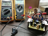
Ian, yes I have tested the board with a 100 khz square wave and there were no ringing. As you say, I am just asking for preventative reasons and to prevent unwanted stuff entering the output. 🙂
Ian, yes I have tested the board with a 100 khz square wave and there were no ringing. As you say, I am just asking for preventative reasons and to prevent unwanted stuff entering the output. 🙂
Well as you have confirmed there is no ringing and there are no known RF issues, then there is nothing to do as Ian rightly says that the inductor-resistor combination isn't necessary on the P3A.
There is a plan here but I think it would be simpler to try capacitive bypassing first if RF ingress seems to be a problem, rather than taking out insurance against a non-problem. The project as it stands is a pretty bulletproof design and probably more widely built and tested for this sort of problem than we can imagine.
Hi Ian, I agree - if there isn't a problem, there's no need to fix it!
- Home
- Amplifiers
- Solid State
- Rod Elliot P3A Layout - Critics