Pete, take a look at the very first paragraph (literally!) of Chapter 4 of the 2nd edition. That's the chapter which systematically develops the BC-1.
Please notice the fourth sentence of the chapter, the one which begins
(emphasis added by me)
I don't yet have the second edition and my suggestion was for an optional network.
..............
It is for the same reason that I am very cautious about using a lead capacitor across the feedback resistor. I seem to recall that Cherry discussed this sort of thing a long time ago in his paper on output networks and feedback networks. Speakers and their cables can act as big antennas for RFI ingress.
..........
Cheers,
Bob
I don’t think that this lead capacitor or even Cherry type of compensation with capacitor from amp output is a way of RFI ingress from speaker and their cables.
Why, because in good designed GNFB amp output impedance (position from where the feedback was taken) is very low, much lower than the speaker cables and output inductor have. This could be even more important then DF. Simple MC is not good enough at higher frequencies, it needs more sophisticated compensation like TPC, TMC or my OITPC to get high Loop Gain throughout whole audio band and beyond.
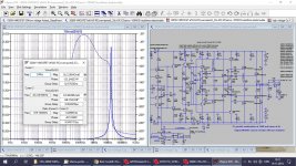
Attached my amp simulation of the output impedance.
Damir
Attachments
I don’t think that this lead capacitor or even Cherry type of compensation with capacitor from amp output is a way of RFI ingress from speaker and their cables.
Why, because in good designed GNFB amp output impedance (position from where the feedback was taken) is very low, much lower than the speaker cables and output inductor have. This could be even more important then DF. Simple MC is not good enough at higher frequencies, it needs more sophisticated compensation like TPC, TMC or my OITPC to get high Loop Gain throughout whole audio band and beyond.
Attached my amp simulation of the output impedance.
Damir
Hi Damir,
The output impedance in a well-designed GNFB amplifier at the point where negative feedback is taken is indeed very low at frequencies well below the ULGF, however it does rise with frequency, as does the output impedance of most any GNFB amplifier. This is not just because of the declining negative feedback, but also because the beta of the output transistors is declining as frequency increases. This is, I admit, an aspect of design wherein I may be over-conservative.
Miller compensation is fine for many amplifiers, but performance can indeed often be improved with more sophisticated compensation techniques like TPC and TMC, I agree. The BC-1 deliberately avoided these refinements in the goal of simplicity. However, it is quite easy to add TPC or TMC to the BC-1 with a couple of simple white wires and an added resistor and capacitor.
Cheers,
Bob
The output zobel shunts the OPS impedance, so it should not matter if it rises. To cause significant demodulation you need a minimum RF voltage across the zobel. 45mV reduces LTP gain by 6db so let's consider that a critical value. 45mV/10ohm zobel = 4.5mA RF current and 20mW into the zobel resistor, assuming the OPS does nothing to mitigate the RFI.
If this were a crystal radio receiver it could cause permanent hearing damage using headphones. So perhaps it is CM RFI we are worried about. I suspect it is the more common type.
If the RFI is common mode, then the input and feedback RF reference nodes should be at the same point along the ground bus carrying the common mode current. We can also perhaps decouple signal/speaker jacks to chassis so that RF will flow across the chassis rather than through the internal circuitry.
I think that most of the time, RF just isn't large enough to cause interference all by itself. It needs something in the amplifier to be susceptible to it. This could be:
1: Collector/drain LC resonance
2: Bypass capacitor resonance
3: Peaking in local feedback loops such as a 2Q CCS.
4: Clapp/Colpitts/etc. parasitic circuits around transistors.
5: Just bad RFI design practice.
However, it is quite easy to add TPC or TMC to the BC-1 with a couple of simple white wires and an added resistor and capacitor.
Hi Bob,
Since I have not fab'd BC-1(AFE)-A1 pcb yet, pending your approval, would it be possible to add in these other comp types as stuffing options, instead of white wires and barnacles. I do not mind, to make these small changes 🙂
That way, one could experiment with these types to determine their need and usefulness.
P.S.
THD-1 <0.001% 1W – 100W, 8Ω or 4Ω load
THD-20 <0.004% 1W – 100W, 8Ω (0.008%, 4Ω)
Just does not seem to be good enough in todays world, we need to keep everyone happy 🙂
Thanks Rick
Last edited:
RF considerations
Hi all,
I think it is worth pointing out, that the much lauded TMC also creates a path from amplifier output to VAS input and output.
Also, we shouldn't assume that the zobel cap and resistor actually behave as such at RF frequencies, particularly if long tracks are associated with them. For this reason, in the past, I use four layer boards with a ground plane.
Regards,
Ian
That is true about TMC, but there is a fairly large resistor in that path, so RFI is less likely to sneak in with much amplitude.
I like to use 2 output Zobels. One before the output coil and relay and one after. The first one must be close to the output transistors to do its best job of enhancing stability. The second one is best placed off the board right across the speaker terminals, although I usually make allowance to put the second one on the PCB right at the output speaker terminals.
Cheers,
Bob
Hi Bob,
Since I have not fab'd BC-1(AFE)-A1 pcb yet, pending your approval, would it be possible to add in these other comp types as stuffing options, instead of white wires and barnacles. I do not mind, to make these small changes 🙂
That way, one could experiment with these types to determine their need and usefulness.
P.S.
THD-1 <0.001% 1W – 100W, 8Ω or 4Ω load
THD-20 <0.004% 1W – 100W, 8Ω (0.008%, 4Ω)
Just does not seem to be good enough in todays world, we need to keep everyone happy 🙂
Thanks Rick
The majority of people who buy the book and circuit boards is going to be serious about
amp design and to offer only simple Cdom comp is rather boring. Good to see that you
are considering a mod to the PCB.
Fans of Bob's book might be interested in a thread I just started
Bob Cordell's Super Gain Clone PCB (LM3886) and a stripped-down version: Compact3886
Bob Cordell's Super Gain Clone PCB (LM3886) and a stripped-down version: Compact3886
Fans of Bob's book might be interested in a thread I just started
Bob Cordell's Super Gain Clone PCB (LM3886) and a stripped-down version: Compact3886
Mark brought his implementation of the Super Gain Clone to Burning Amp, and he did a beautiful job on it. Nice work!
Cheers,
Bob
Are any pictures available of the BC-1 PWB? I am curious of the power supply layout of the entire system of boards. It seems as if there are several boards that make up the amp.
Thanks
Thanks
Are any pictures available of the BC-1 PWB? I am curious of the power supply layout of the entire system of boards. It seems as if there are several boards that make up the amp.
Thanks
Rick and I have not yet finalized the physical design of the BC-1 board set that will be made available. The existing prototype PCBs were on display at Burning Amp. That is a 2-board set. One board contains the IPS, VAS, bias spreader and pre-drivers. The second board, which is physically quite a bit larger, contains the output stage (drivers, 2 output pairs and output network) and all of the protection circuitry. That latter board is too big for some chassis/heat sink implementations, so we are considering whether or not to split off the protection circuitry to a 3rd board.
Cheers,
Bob
When a power transistor dies in an EF, which two terminals short first? I would assume the collector and base junctions fuse first, because most of the heat is generated in the collector junction.
When a power transistor dies in an EF, which two terminals short first? I would assume the collector and base junctions fuse first, because most of the heat is generated in the collector junction.
Good question. I think your reasoning is sound and that you are probably right, but I am not a device guy. I all happens so fast .....
Cheers,
Bob
Well you are correct, I just happen to have a couple of failed TO-3 bjts from a Pioneer SX-1250 that I am servicing, 2SB600, show collector-base shorted, base-emitter still measure okay.
Are any pictures available of the BC-1 PWB? I am curious of the power supply layout of the entire system of boards. It seems as if there are several boards that make up the amp.
In post #9448 I showed a pic of the 2 board set making up BC-1 (left pic) and DH-220C in the right pic. It is the packaging/ chassis construction for BC-1, that is the question as to its usefulness in its current configuration.
https://www.diyaudio.com/forums/sol...lls-power-amplifier-book-945.html#post5843875
The middle pic is a rectifier/reg pcb and the BC-1 front ends.
Last edited:
Well you are correct, I just happen to have a couple of failed TO-3 bjts from a Pioneer SX-1250 that I am servicing, 2SB600, show collector-base shorted, base-emitter still measure okay.
My understanding is the emitter is more heavily doped than the collector and has lower resistance to conduction.
My understanding is the emitter is more heavily doped than the collector and has lower resistance to conduction.
my experience too, collector emitter shorts are common, and in the case of output trannies, the emitter resistors of about 0.22 ohms acted like fuses...
Cyril Bateman's unpublished article on Amp-Speaker cable interactions now available
Download here http://www.waynekirkwood.com/images/pdf/Cyril_Bateman/Bateman_Speaker_Amp_Interaction.pdf
Cyril mentions some RF injection tests on an amp in the article.
Although this is not an easy read it contains some vital information for amplifier builders that few seem to be aware of - the need to add a termination Zobel at the speaker terminals. Bob Codell mentions this in his book but I can't find any previous mention of this on this forum (I don't have page reference for 2nd ed right now, maybe someone can give it).
Why is a speaker cable termination Zobel needed? That's what Cyril tried to explain but never quite uncovered the source of the amplifier oscillation that destroyed 3 of his amps (2 while bench testing with different cables). But he did prove
1) using measurements that the reflected energy from an unterminated speaker cable presents a high return ratio (a transmission line engineers term) and the amplifiers Zobel, and
2) the output inductor does not stop amplifiers from oscillating at a few MHz, and this can destroy some amps (his BJT amps failed but not his lateral amps).
I believe it is as serious as that. It requires more research to get to the bottom of what causes this and maybe if amplifiers can be made that don't oscillate when driving problematic unterminated speaker cables. Is it as simple as adding heavier compensation?
Cheers,
That reminded me of Cyril Bateman's unpublished article on Amplifier-Speaker cable interactions so I forwarded the article to Wayne Kirkwood to update his collection of Cyril's articles here Re: Cyril Bateman Capacitor Sound Archive - Pro Audio Design Forum and the Amplifier-Speaker cable interaction article Parts 1 & 2 (previously only part 1 was available)..The output zobel shunts the OPS impedance, so it should not matter if it rises. To cause significant demodulation you need a minimum RF voltage across the zobel. 45mV reduces LTP gain by 6db so let's consider that a critical value. 45mV/10ohm zobel = 4.5mA RF current and 20mW into the zobel resistor, assuming the OPS does nothing to mitigate the RFI.
Download here http://www.waynekirkwood.com/images/pdf/Cyril_Bateman/Bateman_Speaker_Amp_Interaction.pdf
Cyril mentions some RF injection tests on an amp in the article.
Although this is not an easy read it contains some vital information for amplifier builders that few seem to be aware of - the need to add a termination Zobel at the speaker terminals. Bob Codell mentions this in his book but I can't find any previous mention of this on this forum (I don't have page reference for 2nd ed right now, maybe someone can give it).
Why is a speaker cable termination Zobel needed? That's what Cyril tried to explain but never quite uncovered the source of the amplifier oscillation that destroyed 3 of his amps (2 while bench testing with different cables). But he did prove
1) using measurements that the reflected energy from an unterminated speaker cable presents a high return ratio (a transmission line engineers term) and the amplifiers Zobel, and
2) the output inductor does not stop amplifiers from oscillating at a few MHz, and this can destroy some amps (his BJT amps failed but not his lateral amps).
I believe it is as serious as that. It requires more research to get to the bottom of what causes this and maybe if amplifiers can be made that don't oscillate when driving problematic unterminated speaker cables. Is it as simple as adding heavier compensation?
Cheers,
- Home
- Amplifiers
- Solid State
- Bob Cordell's Power amplifier book