Here is a blast form the past. This was my FX8 Bimo Mod by Prasi that I built maybe 5 years ago. Wow, time flies. I set it up on a plank (as usual for verification builds) and ran as Class AB, although bias is pretty high so it runs quite warm. A few years went by, and I later installed it in a DIYA 4U Dissipante case and ran it at +/-24v and 1.25A bias current in full Class A. It worked well and sounded great. It is a lateral FET amp, so pushing bias into Class A is fine without fear of thermal runaway. Very nice layout by Prasi - awesome amp. Highly recommended.
Hi x,
Yes, I saw those photos and your class -A build when I was browsing through for info for my build...
Very nicely done. I always kept promising myself that I will build this amp, but never really did. Better late than never.
Take care.
regards
prasi
Chinese boardhouses are accepting orders but shipping is on hold for India.
Indian ones are all closed..😱
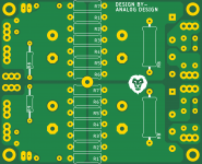
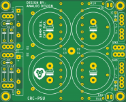
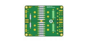
here are gerbers and sch... you could use a small aluminium plate as heatsink ( shown as hatched lines ) for the rectifiers (insulate rectifiers if using such single heatsink).
Thanks Prasi, yes I see that Chinese board houses are not accepting any orders if shipping to India. Nice idea of having the big wattage resistors underneath the board as well as the bleeder resistors, then we need to install slightly big spacers for the board.
If using onboard bridge rectifiers B1/B2 which needs to be isolated if using a single aluminium plate as heat sink. Then in that case I can skip the 4 diodes (marked CS,CS',CX, CX') and a pair of resistors (marked RS,RS') directly connect the transformer secondaries to the 3 hole marked 4 pins.
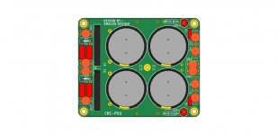
If I use offboard bridge rectifiers then I can connect the +/- from the bridge rectifiers directly to the +/- near the either side of the 2 bridge rectifiers. What is the purpose of RB and RB' which I can see underneath? I thought of using 1 of 0.22 or 0.33R 5W cement type resistors on each side (R7 and R1' so that I can install them on top of the board rather than underneath) with 4 capacitors of 10000uf 63v as my usage is going to be not more than 30v@5A AC transformer.
No, please study the schematic carefully...
1. using on-board rectifiers b1 /b2:
cs/cx , cx', cs' and rs , rs' are the quasimodo snubber components (optional).
2. off board rectifiers:
connect the off-board first bridge rectifier's +ve WIRE to the B1+ terminal towards the top AND rectifier's - wire to the B1's - terminal.
connect the off-board second bridge rectifier's + wire to the B2's + terminal and then rectifier's - wire to the B2's - terminal.
RB and RB' are the bleeder resistors...
R1 to R7 on positive and R1'-R7' on the negative side are in parallel...
So you would be better off using 1 ohm , 1W to 2W resistors.
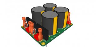
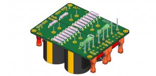
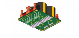
I will make a 3D on how to mount components...
edit: 3-d pics attached
1. using on-board rectifiers b1 /b2:
cs/cx , cx', cs' and rs , rs' are the quasimodo snubber components (optional).
2. off board rectifiers:
connect the off-board first bridge rectifier's +ve WIRE to the B1+ terminal towards the top AND rectifier's - wire to the B1's - terminal.
connect the off-board second bridge rectifier's + wire to the B2's + terminal and then rectifier's - wire to the B2's - terminal.
RB and RB' are the bleeder resistors...
R1 to R7 on positive and R1'-R7' on the negative side are in parallel...
So you would be better off using 1 ohm , 1W to 2W resistors.
I will make a 3D on how to mount components...
edit: 3-d pics attached
Attachments
Last edited:
Thanks Prasi, I think I understood the schematic correctly but maybe did not put the markings correctly for the offboard rectifiers if I am using. I will better use onboard rectifiers looking at the small form factor of the board 🙂
Regarding the R1-7 and R1'-R7' you are suggesting to use either 1R of 1W/2W resistors as they are parallel rather than using one of 0.1R 5W resistor like this 10pcs BPR56 5W 0.1 0.15 0.22 0.25 0.33 0.5 ohm Non inductive Ceramic Cement Resistor 0.1R 0.15R 0.22R 0.25R 0.33R 0.5R|Resistors| | - AliExpress as 1R of 8 in parallel makes it to 0.12R. As I was thinking of using the cement resistor on top of the board and for better heat dissipation.
Thanks again
you could use 1 of 0.1-0.22 ohm, 5W resistor or 7 of 1ohm, its almost same...
its up to you to use it as per your convenience and space in chassis and available components... All the best.
its up to you to use it as per your convenience and space in chassis and available components... All the best.
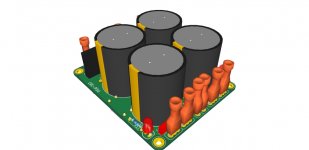
Also a bridge rectifier like this - 5PCS 25A 1000V diode bridge rectifier KBU2510|Rectifiers| | - AliExpress should be sufficient looking at the 3D image should easily fit and with the mounting hole we can put a small aluminium plate with some kind of insulation if both the rectifiers are mounted on the same plate. I am not sure if I have to use the aluminium plate as I will not be using more than 5A secondary trafo with this board for now in my class AB builds. What do you think?
thanks
thanks
Those legs seem to be equispaced, i had in mind some thing like this. https://www.mouser.in/datasheet/2/427/pb3506-1767492.pdf
for aliexpress, MCIGICM 5PCS 35A 1000V diode bridge rectifier gbj3510|bridge rectifier|diode bridge rectifier|diode bridge - AliExpress
For normal listening, you can get away without using heatsink...
for aliexpress, MCIGICM 5PCS 35A 1000V diode bridge rectifier gbj3510|bridge rectifier|diode bridge rectifier|diode bridge - AliExpress
For normal listening, you can get away without using heatsink...
Last edited:
Those legs seem to be equispaced, i had in mind some thing like this. https://www.mouser.in/datasheet/2/427/pb3506-1767492.pdf
for aliexpress, MCIGICM 5PCS 35A 1000V diode bridge rectifier gbj3510|bridge rectifier|diode bridge rectifier|diode bridge - AliExpress
For normal listening, you can get away without using heatsink...
Thanks Prasi, I found similar one as well like the PB3510 🙂
5PCS GBJ35M KBJ3510 PB3510 integrated circuit|integrated circuit|circuit integre| - AliExpress
I think sinking them with an aluminium strip seems to be tricky with the other componens and AC wiring being very close to the rectifiers. Maybe we can lift the rectifiers up a little bit and use the aluminium strips and the plastic isolation To-220 should fit with couple of silicon thermal strips in between with some grease.
Otherwise your boards look perfect and awesome for anyone to build and use, hats off

Last edited:
Meanwhile I am well on the way to building Apex FX-8 Bimo Mod amp. see attached pic from yesterday.
Today I fitted output transistors (2SK and 2SJ) and tested for bias and offset.
All ok...
I am also building a case with upc1237 protect , CRC PSU and VU meter and ESP P88 preamp with volume control. All the pcbs are designed by me.🙂
Because of the lock down in India, I am finally able to complete some of the long pending projects.
PCBs for the Bimo amp are kindly donated by Ivanlukic... Thanks Evan...
regards
prasi
Very nice build, prasi!
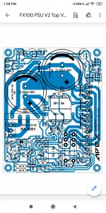
Apex fx 100 psu
Hello guys I made fx 100.every components I checked before set on pcb after soldier.but psu protection not working .like short circuit.and dc also .plz suggest me .how i sold first I give 35-0-35 also on 50 0 50 ac volt
Hello guys I made fx 100.every components I checked before set on pcb after soldier.but psu protection not working .like short circuit.and dc also .plz suggest me .how i sold first I give 35-0-35 also on 50 0 50 ac volt
Attachments


No, please study the schematic carefully...
1. using on-board rectifiers b1 /b2:
cs/cx , cx', cs' and rs , rs' are the quasimodo snubber components (optional).
2. off board rectifiers:
connect the off-board first bridge rectifier's +ve WIRE to the B1+ terminal towards the top AND rectifier's - wire to the B1's - terminal.
connect the off-board second bridge rectifier's + wire to the B2's + terminal and then rectifier's - wire to the B2's - terminal.
RB and RB' are the bleeder resistors...
R1 to R7 on positive and R1'-R7' on the negative side are in parallel...
So you would be better off using 1 ohm , 1W to 2W resistors.
I will make a 3D on how to mount components...
edit: 3-d pics attached
Nice compact layout, Prasi! We could use the active bridge boards for the rectifiers. Even for Class AB, I have found that an LT4320 reduces the diode switching noise, and really, eliminates the need for the snubber. This is all possible because the switching is at zero-crossing vs 0.6v (Si diode switching), hence no noise generated. This results in a cleaner or "blacker blacks" noise background. Your GBJ format active bridge boards are perfect for this. The only issue is added expense of a $7 LT4320 chip x 2, plus nominal cost of the active bridge board.
Just pointing this out as I have noticed a substantial improvement in sound quality, even with non Class A amps whne LT4320 is part of the PSU.
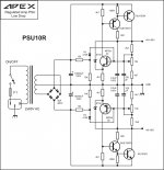
Hello brother, yes this PCB layout correct. Only one change, 2k2 resistance change with 1k or 820R or 680R.
I made that PCB on https://www.diyaudio.com/forums/sol...mate-fidelity-amplifier-1055.html#post5515173
Changed resistance value mark below
Regards
Hi,
Do you have a PDF file of your pcb, or size of this AX11 pcb?
Thank you in advance.
Best regards
Hi,
Do you have a PDF file of your pcb, or size of this AX11 pcb?
Thank you in advance.
Best regards
Hello Alain, this is not my PCB layout, it's Mr. Mile design. I have not PDF of that PCB but you can download PCB image from below link and PCB size 60mm x 70mm.
Here is your link:
100W Ultimate Fidelity Amplifier
Regards
Gurpreet
Nice compact layout, Prasi! We could use the active bridge boards for the rectifiers. Even for Class AB, I have found that an LT4320 reduces the diode switching noise, and really, eliminates the need for the snubber. This is all possible because the switching is at zero-crossing vs 0.6v (Si diode switching), hence no noise generated. This results in a cleaner or "blacker blacks" noise background. Your GBJ format active bridge boards are perfect for this. The only issue is added expense of a $7 LT4320 chip x 2, plus nominal cost of the active bridge board.
Just pointing this out as I have noticed a substantial improvement in sound quality, even with non Class A amps whne LT4320 is part of the PSU.
Where can we find the LT4320 at $7? Can you please provide the link?
Edit: Ok I found the SMD one for $7.13 on mouser but the through hole is around $8
thanks
Last edited:
Dear sirYes, also you can use BF471/472 in TO126 case or BF871/872... and there is many 2SA/SC, 2SB/SD...
Please solve my problem is that when supply is given then both bc639 and 640 emitter resistances 47 ohm smoke .my supply is given by series 100watt bulb.method.thanking you
Yours ever
I am Downloading all these circuit please tell me this is all correct and what transformer shud be used for best performance and stability so that no harm will caused to circuit
+/-24V DC is the lowest operating voltage, if you have +/-32V DC you can use this amp but power will be about 40W on 8R load.
Regards
Dear Sir apex..I am very new here and join this just to make your amplifier ax14 I ha e found all your posted circuit diagram regarding ax14 ..My question is that what transformer should I purchase to drive this amp stereo version because I am gonna make a teri version
- Home
- Amplifiers
- Solid State
- 100W Ultimate Fidelity Amplifier